Drowning alarm apparatus in swimming pool

A technology for alarms and swimming pools, applied to alarms, instruments, and electrical transmission signal systems, etc., can solve problems such as lack of scientific equipment, and achieve the effects of ensuring life safety, large user capacity, and small size

Inactive Publication Date: 2008-06-11
晋捷
View PDF0 Cites 34 Cited by
  • Summary
  • Abstract
  • Description
  • Claims
  • Application Information

AI Technical Summary

Problems solved by technology

At present, domestic drowning monitoring for swimmers mostly relies on rescue personnel to determine through naked eye observation. There is no scientific equipment and means to provide rescue personnel with timely and effective drowning information

Method used


Image

  • Drowning alarm apparatus in swimming pool
  • Drowning alarm apparatus in swimming pool
  • Drowning alarm apparatus in swimming pool

Examples


Embodiment 1

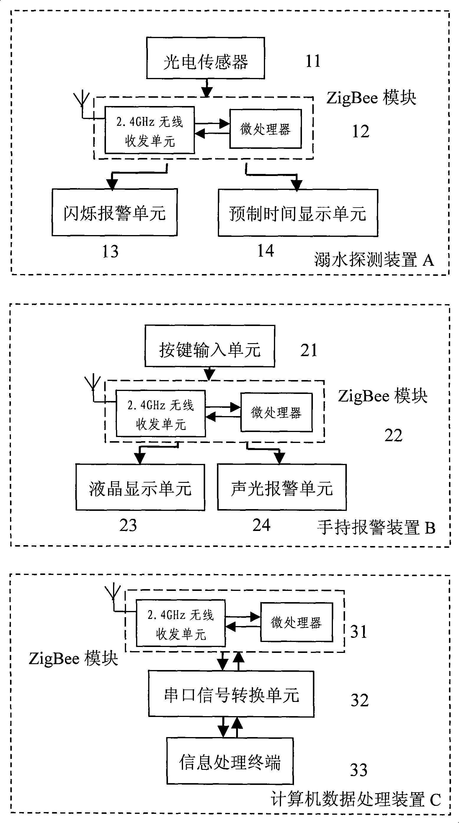
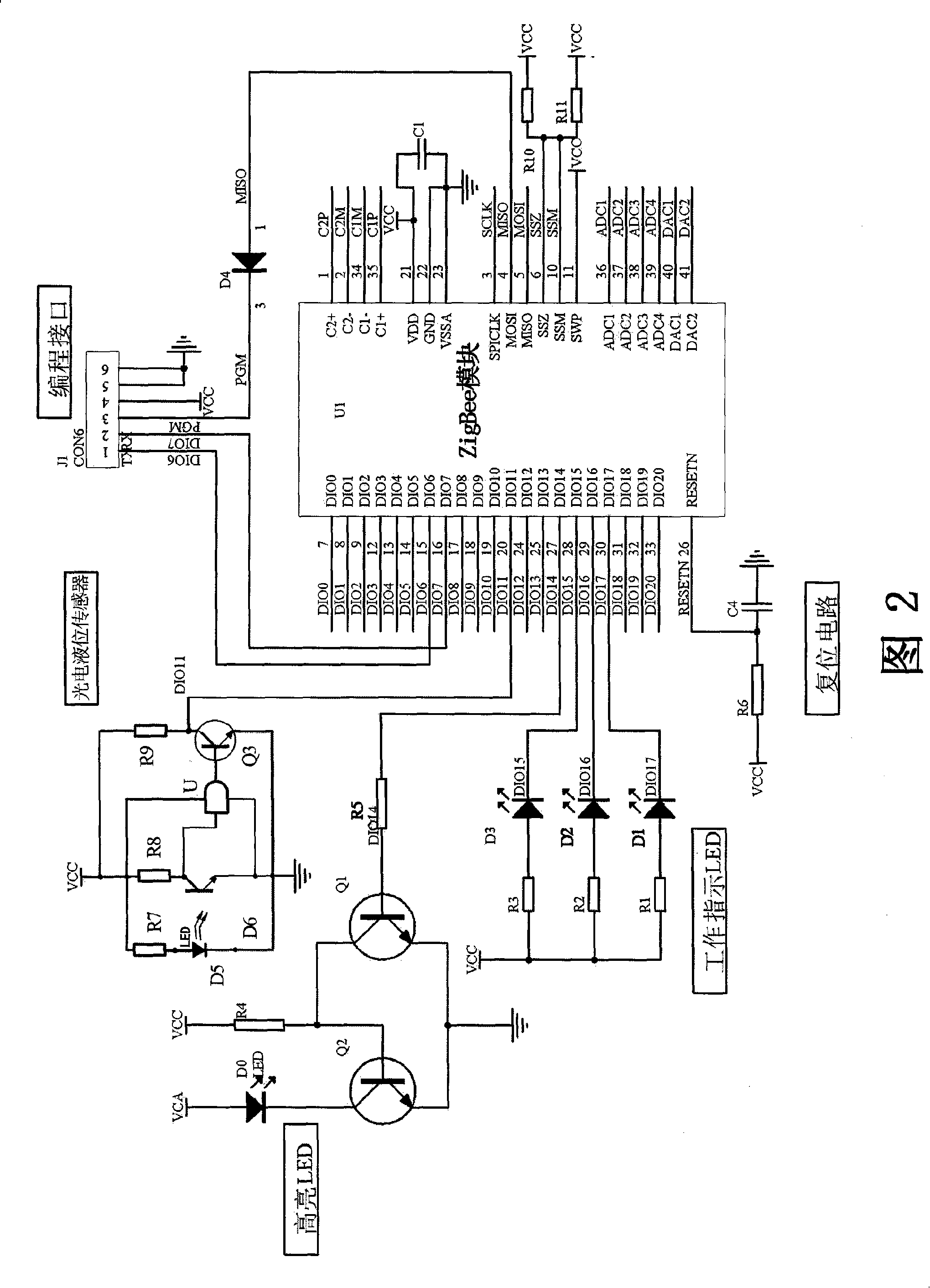
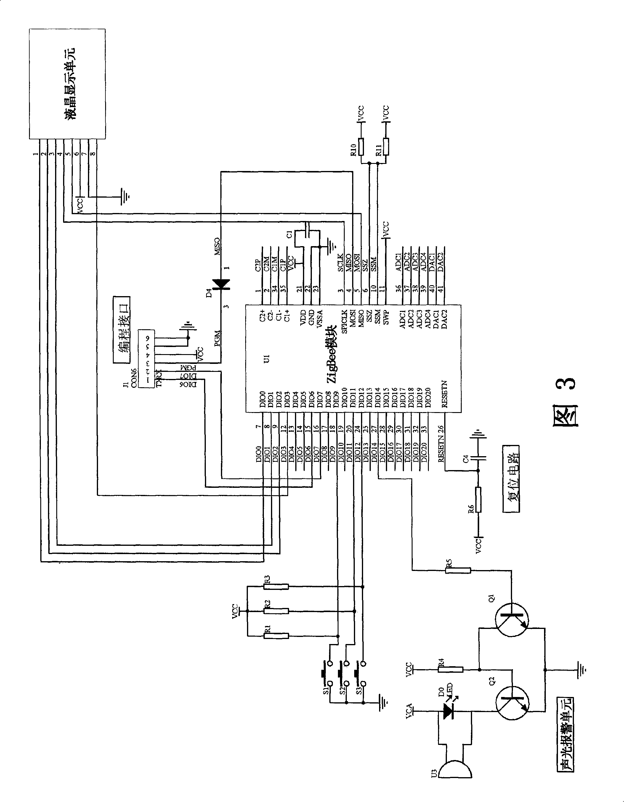
[0039] Example one, see figure 1 As shown in FIG. 4 , a swimming pool drowning alarm device of the present invention is composed of three parts: a drowning detection device A, a hand-held alarm device B and a computer data processing device C.

[0040] The drowning detection device A is composed of a photoelectric liquid level sensor 11, a ZigBee module 12, a flashing alarm unit 13 and a preset time display unit. The output of the photoelectric liquid level sensor 11 is connected to the input control terminal of the ZigBee module 12, so that the drowning judgment signal of the former is used as the signal of the latter to control the timing circuit and transmit a data packet, which contains the address code of the drowning detection device A, battery The voltage information is transmitted at a certain time interval through the 2.4GHz wireless transceiver unit; one output port of the ZigBee module 11 is connected to the input end of the flashing alarm unit 13 as a start signal ...

Embodiment 2

[0062] Example 2, see Figure 5 As shown, a swimming pool drowning alarm of the present invention is composed of two parts: a drowning detection device A and a hand-held alarm device B. The difference from the first embodiment is that the data packets transmitted by the drowning detection device A are only received by the handheld alarm device B; the preset drowning alarm time of the drowning detection device A can only be set by the handheld alarm device B. This embodiment is mainly suitable for families, monitoring 1 to 3 drowning detection devices A.

Embodiment 3

[0063] Example three, see Image 6 As shown, a swimming pool drowning alarm of the present invention is composed of two parts: a drowning detection device A and a computer data processing device C. The difference from the first embodiment is that the data packets transmitted by the drowning detection device A are only received by the handheld alarm device C; the preset drowning alarm time of the drowning detection device A can only be set by the handheld alarm device C. This embodiment is mainly suitable for large and medium-sized swimming places to monitor more than three drowning detection devices A.


PUM


Abstract

The invention discloses a swimming pool drowning alarm device which consists of a drowning detection device A, a handhold alarm device B and a computer data processing unit. The drowning detection device A is worn on the head of a swimmer, the handhold alarm device B is used by the lifeguard, the computer data processing unit C is used by the management personnel of the swimming pool. Under normal condition, the drowning detection device A sends signals to the handhold alarm device B and the computer data processing unit C at fixed time. When the head of the swimmer is immerged into the water, the drowning detection device A does not send any signal, a timing circuit of the drowning detection device A and the handhold alarm device B as well as the computer data processing unit C is started, the swimmer is judged as the drowning if the given time reaches and the swimmer still does not come out from water. At this time, the drowning detection device A flashes and flickers to display the position of the drowner, the handhold alarm device B and the computer data processing unit C make a sound-light alarm to remind the crowd around, the lifeguard and the management personnel of the swimming pool to implement rescue to the drowner.

Description

technical field [0001] The invention relates to a swimming pool drowning alarm, in particular to an alarm which can automatically identify swimmer safety or drowning. Background technique [0002] Statistics show that drowning has become the number one cause of unnatural deaths among children aged 3-14, and it is distressing that drownings often occur even in standard swimming pools in cities. At present, most domestic drowning monitoring of swimmers relies on ambulance personnel, who are determined by naked eye observation. There is no scientific equipment and means to provide timely and effective drowning information to ambulance personnel. The patents that can be retrieved in China are basically based on swimmers' self-rescue or standardizing swimmers' swimming postures. [0003] In July 2006, a novelty search was carried out on the technical scheme of the swimming pool drowning alarm in the Patent Search and Consulting Center of the State Intellectual Property Office, a...

Claims


Application Information

Patent Timeline
Patent Type & Authority Applications(China)
IPC IPC(8): G08B21/08G08B7/06
Inventor 晋捷
Owner 晋捷
Why Eureka
Try Eureka