
Antenna device

An antenna device and antenna technology, applied in the field of communication systems, can solve the problems of increased cost, inconvenience, and reduced service life of the antenna device 1, etc.

Inactive Publication Date: 2008-06-11
INVENTEC CORP
View PDF0 Cites 6 Cited by
  • Summary
  • Abstract
  • Description
  • Claims
  • Application Information

AI Technical Summary

Problems solved by technology

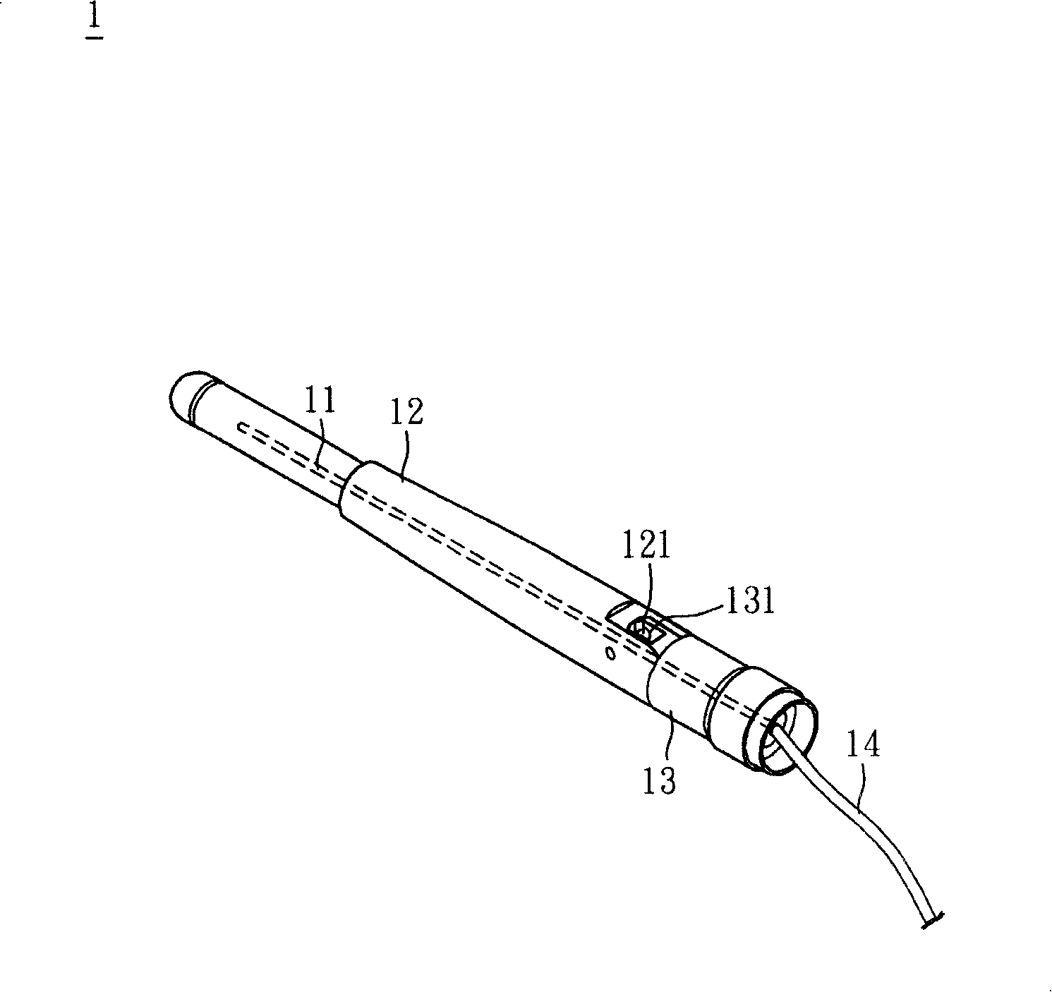
[0004] However, when the antenna cover 12 rotates relative to the antenna base 13, the antenna body 11 will be bent due to the drive of the antenna cover 12 and the antenna base 13, and the antenna body 11 will be easily damaged.
In addition, the pivot joint between the pivot shaft 121 and the pivot hole 131 is easy to loosen due to long-term wear and tear, which makes the positioning of the antenna device 1 difficult and reduces the life of the antenna device 1.
[0005] In addition, in order to prevent the antenna body 11 from being bent due to the antenna cover 12 and the antenna base 13, the industry must replace the antenna body 11 with complex mechanical components at the turning point, wherein these complex mechanical components must have electrical connections and function of rotation, which in turn leads to an increase in the cost of the antenna device 1
[0006] This shows that above-mentioned existing antenna device obviously still has inconvenience and defect in structure and use, and urgently needs to be further improved
In order to solve the above-mentioned problems, the relevant manufacturers have tried their best to find a solution, but no suitable design has been developed for a long time, and the general products do not have a suitable structure to solve the above-mentioned problems. This is obviously related. The problem that the industry is eager to solve

Method used


Image

  • Antenna device
  • Antenna device
  • Antenna device

Examples


Embodiment Construction

[0050] In order to further explain the technical means and effects of the present invention to achieve the intended purpose of the invention, the specific implementation, structure, characteristics and effects of the antenna device proposed according to the present invention will be described in detail below in conjunction with the accompanying drawings and preferred embodiments. The description is as follows.

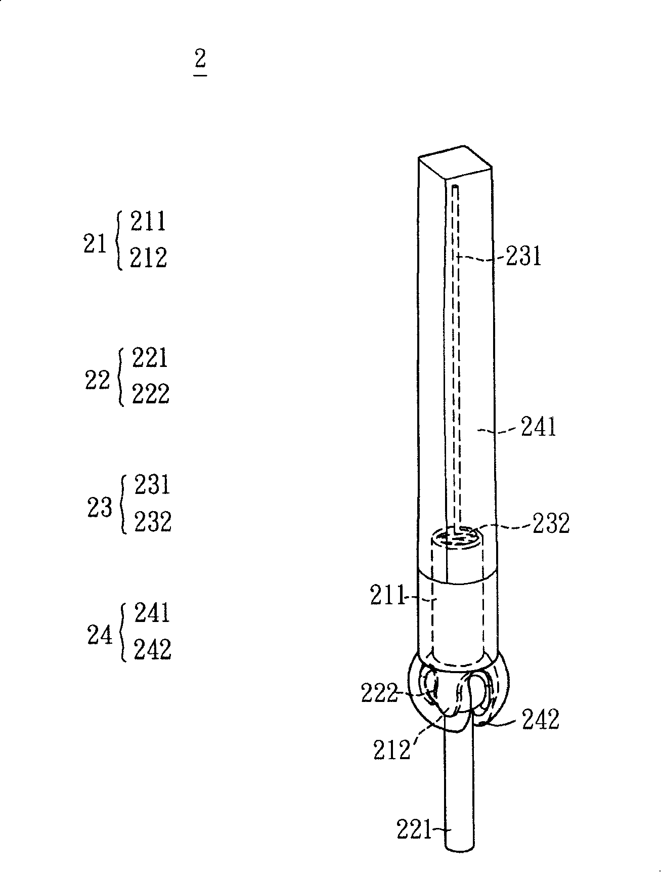
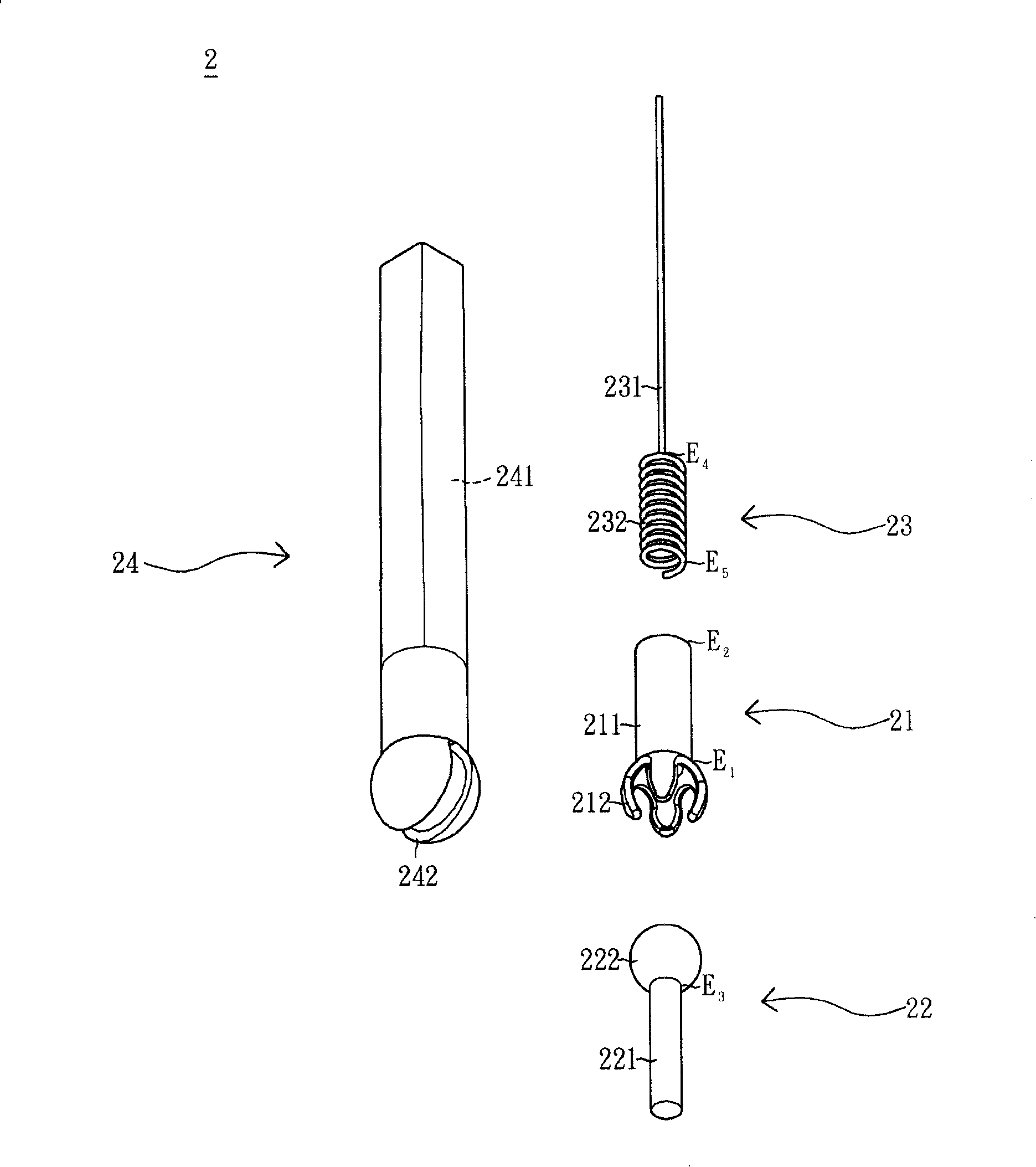
[0051] Please also see figure 2 and image 3 As shown, the antenna device 2 according to the preferred embodiment of the present invention includes an auxiliary connecting unit 21 , a rotating connecting unit 22 , an antenna body 23 and a casing 24 .

[0052] The auxiliary connection unit 21 has a tube portion 211 and a plurality of claw portions 212 . The tube part 211 has a first end E1 and a second end E2 , and the claw part 212 is extended from the first end E1 of the tube part 211 . Wherein, the shape and quantity of the claws 212 can be designed differently a...


PUM


Abstract

The invention relates to an antenna device, comprising an auxiliary connection unit, a rotating connection part, an antenna body and a shell. The auxiliary connection unit is provided with a pipe part and a plurality of claw parts, wherein the pipe part is provided with a first end and a second end, the claw parts are extended and arranged on the first end of the pipe part; the rotating connection unit is provided with a pole part and a ball part, wherein the pole part is provided with a third end which is connected with the ball part which has one part held by the claw parts; the antenna body is at least provided with a radiation part and an elastic part which is provided with a forth end and a fifth end, with the forth end being connected with the radiation part, and is inserted into the pipe part to press the fifth end of the elastic part to be connected with the ball part; the shell is provided with a receiving space and an opening, with the receiving space accommodating the antenna body, the auxiliary unit and the rotating connection unit; one part of the pole part is extended out of the shell through the opening. The antenna device of the invention is not susceptible to damages and low in cost.

Description

technical field [0001] The invention relates to a communication system, in particular to an antenna device. Background technique [0002] With the development of communication technology, people can transfer information to each other through the communication system. The antenna device is an important component used to transmit and receive electromagnetic wave energy in the communication system. If there is no antenna device, the communication system will not be able to transmit and receive. Information. Therefore, the role of the antenna device is an indispensable part of the communication system. [0003] see figure 1 As shown, the conventional antenna device 1 includes an antenna body 11 , an antenna cover 12 and an antenna base 13 . The antenna cover 12 is provided with the antenna body 11, and the antenna body 11 is electrically connected to a feed-in terminal 14 through the antenna base 13, wherein the antenna cover 12 has a pivot shaft 121, and the antenna base 13 ...

Claims


Application Information

Patent Timeline
IPC IPC(8): H01Q1/12H01Q3/02H01Q9/30H01Q1/42H01Q1/20
Inventor 黄政兴
Owner INVENTEC CORP
Learn More