
One-way power output minitype speed reducing motor

A technology of miniature gear motor and power output, which is applied in the direction of electrical components, electromechanical devices, electric components, etc., to achieve the effects of unique structure, expanded application range, and low manufacturing cost

Inactive Publication Date: 2008-06-11
韩选民 +1
View PDF0 Cites 1 Cited by
  • Summary
  • Abstract
  • Description
  • Claims
  • Application Information

AI Technical Summary

Problems solved by technology

[0003] The purpose of the present invention is to solve the problem that the output shaft of the existing miniature geared motor will output power in the forward and reverse directions, and provide a one-way power output miniature geared motor to expand the application range of the miniature geared motor

Method used


Image

  • One-way power output minitype speed reducing motor
  • One-way power output minitype speed reducing motor

Examples


Embodiment Construction

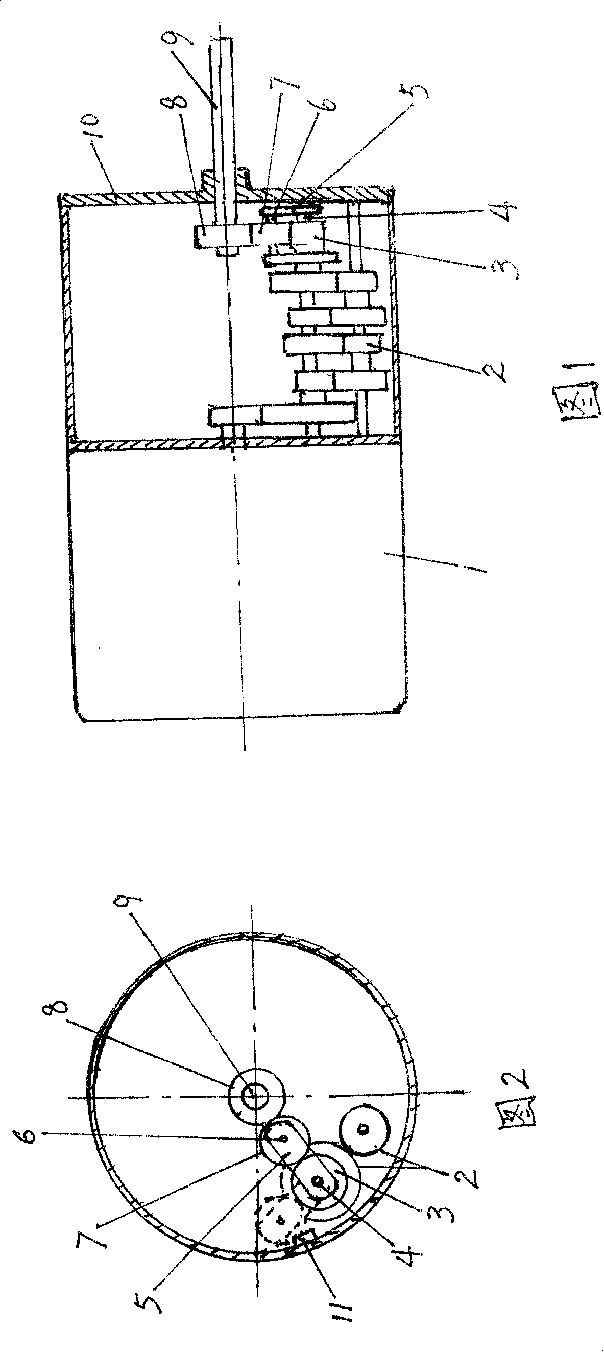
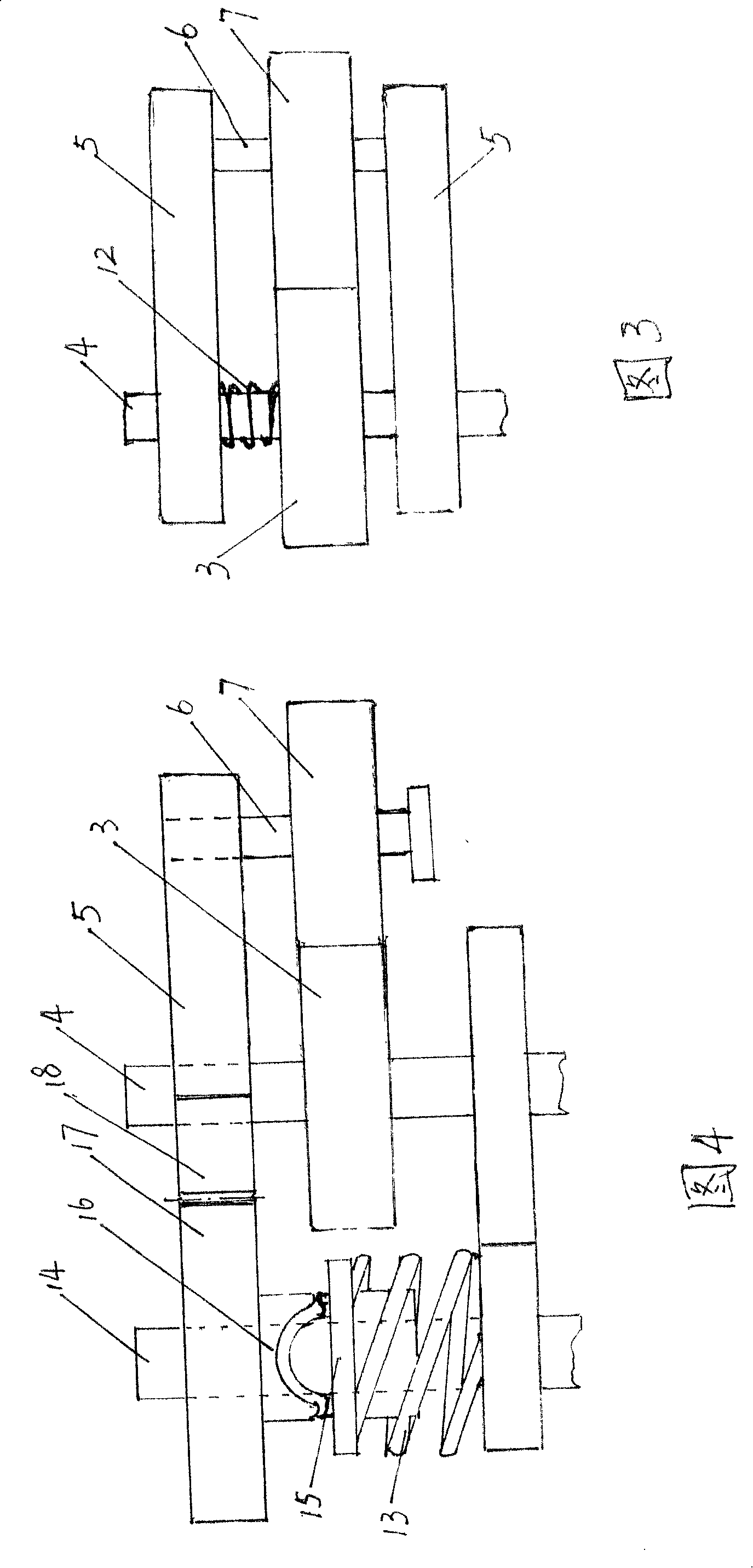
[0017] Referring to Fig. 1 and Fig. 2, the present invention has the basic structure of an ordinary geared motor, including a motor 1 and a reducer 2 connected with the motor, the front end cover 10 of the reducer 2 is equipped with an output shaft 9, and the tail end of the output shaft 9 Transmission gear 8 is fixedly installed. In particular, the following ingenious improvements are made in the present invention: a transition gear 7 is added between the final gear 3 of the reducer and the gear 8 at the tail end of the output shaft, and the transition gear 7 passes through the shaft 6 (move fit assembly) , is installed on the swivel arm 5, and swivel arm 5 can be single arm, is better to make upper and lower double-arm structure (seeing figure 1). The tail end of the rotating arm 5 is rotationally connected with the spindle 4 of the speed reducer. The tail end of the rotating arm 5 can also be rotationally connected with the front end cover 10 of the speed reducer 2 by usin...


PUM


Abstract

The invention relates to a motor improvement technique, being a one-way power output mini gear motor; the invention has a mini motor and a gear decelerator in butt joint with the mini motor; an output axle is arranged through the front end cover of the decelerator and a drive gear is fixed at the tail end of the output axle, in particular to a transmission gear added between the gear at the output axle tail end and the final drive gear of the decelerator; the transmission gear is arranged on a rotary arm with free rotation on the rotary arm; the tail end of the rotary arm is pivotally connected with the single-center axle or the front end cover of the decelerator; the invention solves the problem that the output axle of the motor exports positive and negative power when positively and negatively electrifying common mini gear motor, incapable of meeting special requirements that only one-way output power from motors are needed; the invention has the advantages of delicate design, simple structure, and application in a plurality of places where only one-way output power from motors are required, especially for upward and downward winding curtain driving motor.

Description

(1) Technical field: [0001] The invention relates to the improvement technology of a micro motor, in particular to a unidirectional power output micro reduction motor. (two) background technology: [0002] Existing miniature geared motors are made up of a motor and a reducer connected as a whole. When forward and reverse energized, its output shaft rotates forwardly and reversely through the reducer, and both forward and reverse will output power. This characteristic prevents the miniature geared motor from being used in some special occasions, such as the upper and lower roller blind mechanism. Since the diameter of the roller blind is constantly changing during the movement of the upper and lower roller blinds, the upper and lower drive motors cannot be synchronized. A synchronous auxiliary mechanism or a complex control system must be used to solve the "synchronization" problem, which will inevitably complicate the roller shutter mechanism, increase the cost, and reduce t...

Claims


Application Information

Patent Timeline
Patent Type & Authority Applications(China)
IPC IPC(8): H02K7/116
Inventor 韩选民方水生
Owner 韩选民
Learn More