
Weatherstrip with ventilation openings

A technology of sealing strips and air holes, which is applied in the direction of engine sealing, sealing devices, engine components, etc., can solve the problems of shortening the life of components and easy penetration of dust, and achieve the effect of increasing stability

Inactive Publication Date: 2008-06-11
贝德杰流星橡胶材料合成树脂有限公司及两合公司
View PDF0 Cites 7 Cited by
  • Summary
  • Abstract
  • Description
  • Claims
  • Application Information

AI Technical Summary

Problems solved by technology

In this case, there is a disadvantage that not only dirt easily penetrates into the structure of the sealing part in this way
Such a situation not only has a very adverse effect on the appearance of the sealing strip (depending on the local distortion, which appears as the result of uneven distribution of tensile forces), but also locally produces very large mechanical stresses. stress, which will shorten the life of the part

Method used


Image

  • Weatherstrip with ventilation openings

Examples


Embodiment Construction

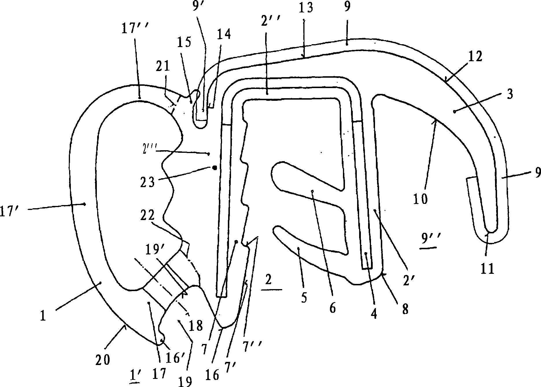
[0018] The profile is a side-by-side structure, which is arranged side by side by a hollow profile-shaped sealing part 1, a U-shaped fastening part 2, and a strip 3 formed on the side of the fastening part 2, wherein the strip 3 mainly constitutes the covering plate.

[0019] A similar U-shaped metal reinforcement 4 is provided on the fastening part 2 and is to be positioned on a flange (not shown in the figure) which is attached to the edge of the opening in the vehicle. In order to stabilize the fitting of the fastening part 2 on this flange, flexible tongues 5, 6 are provided on the inner surface of the fastening part, which generally extend from the right branch 2' in a mutual direction. Parallel spacings extend out and, relative to the U-shaped profile of the fastening part 2 , inwards in the direction towards the profile base 2 ″. In addition, on the inside of the fastening part 2 opposite the flexible tongues 5 , 6 Above, a saw-tooth-shaped structure 7 is provided, whi...


PUM


Abstract

The invention relates to a weatherstrip, which is to be placed onto the flange of the edge of the opening of a vehicle and which is made of a side-by-side arrangement of a tubular sealing section (1), of a U-shaped fastening section (2) and of a strip (3), which is shaped onto the side of the fastening section (2) and which, together with a limb (2') of the fastening section (2), circumscribes a cavity (9 ) open toward the underside (1') of the weatherstrip. The cross-sectional profile of the sealing section (1) is partially formed by the limb (2''') of the fastening section (2) facing the former. Ventilation holes (18) are located on the underside of the weatherstrip, which faces said edge and which forms an area of the greatest wall thickness of the sealing section (1). This arrangement of the ventilation opening is advantageous in that this results in almost no negative influence upon the flexural rigidity of the cross-sectional profile so that the weatherstrip can also be placed along small radii of curvature without the risk of the profile collapsing. To this end, the ventilation openings are located on an underside facing the edge without having any negative influence upon the visual appearance.

Description

Technical field [0001] The invention relates to a sealing molding (weather stripping) as claimed in the preamble of claim 1 . Background technique [0002] There are side-by-side sealing moldings in the prior art. For example, the applicant's company provides such products. The sealing moldings of this structure are composed of hollow special-shaped and / or tubular sealing parts arranged side by side and U-shaped sealing parts. Consisting of a solid part, this sealing strip is to be positioned on a circumferential flange, such as a door frame of a motor vehicle. [0003] The design of the fastening part is primarily for assembly. It should be designed to be reliable to avoid inadvertent detachment from the flange. At the same time, the sealing strip should usually also have a shock-absorbing function. It achieves this function by forming a buffer area between metal parts that are arranged to move relative to each other - such as the door frame and the door edge. In the clos...

Claims


Application Information

Patent Timeline
Patent Type & Authority Applications(China)
IPC IPC(8): B60J10/00B60J10/08
CPCB60J10/08B60J10/0065B60J10/0005B60J10/0034B60J10/0008B60J10/242B60J10/16B60J10/17B60J10/32B60J10/80
Inventor J·许特布罗伊克P·策拉措
Owner 贝德杰流星橡胶材料合成树脂有限公司及两合公司
Learn More