
Multi-functional electric tools

A power tool and multi-functional technology, which is applied in the direction of manufacturing tools, portable motorized devices, metal processing equipment, etc., can solve the problem that multi-functional power tools do not appear

Inactive Publication Date: 2008-06-18
CHANGZHOU SAIDI ELECTRIC MFG +1
View PDF0 Cites 20 Cited by
  • Summary
  • Abstract
  • Description
  • Claims
  • Application Information

AI Technical Summary

Problems solved by technology

[0003] Electric tools in rotary mode (the tool rotates relative to the workpiece) have multi-functional electric tools that change the tool, but reciprocating mode (the tool reciprocates relative to the workpiece) electric tools are still available through the multi-functional electric tool that replaces the tool. did not appear

Method used


Image

  • Multi-functional electric tools
  • Multi-functional electric tools
  • Multi-functional electric tools

Examples


Embodiment Construction

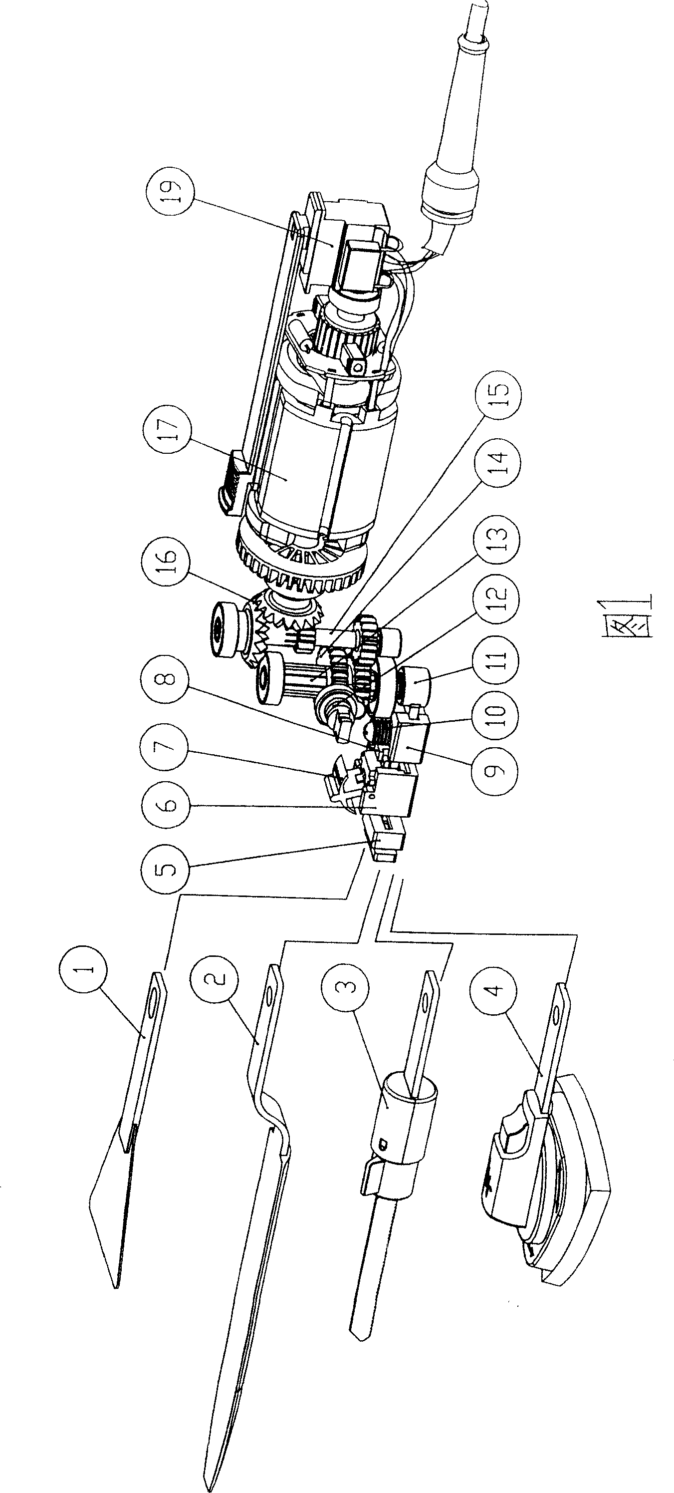
[0016] The details of the structure and the working conditions of the present invention will be described in detail below with reference to the accompanying drawings.

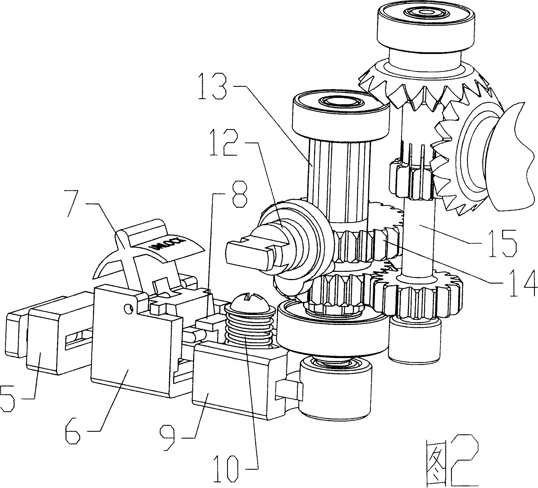
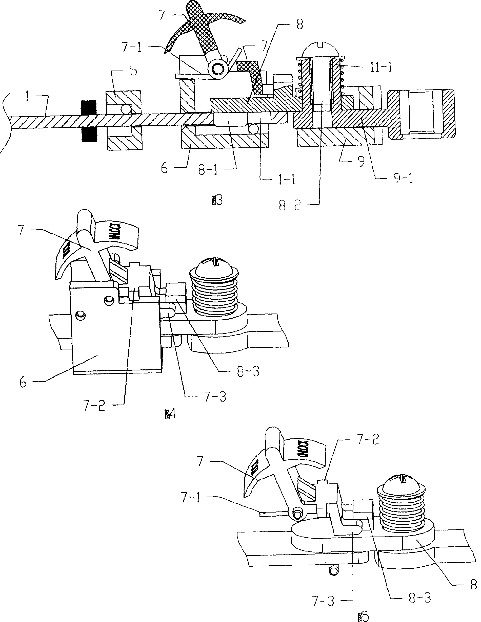
[0017] In FIG. 1 , the tool loading and unloading mechanism includes a front tool rest 5 , a rear tool rest 6 , a sliding plate 8 , a lever 7 , and the like. A hole 1-1 is opened at the rear end of the handle of the tool 1, and the handle of the tool 1 passes through the through holes 5-1 and 6-1 respectively opened on the front tool rest 5 and the rear tool rest 6 and the front tool rest and the rear tool Frame sliding connection. The front end of the sliding plate 8 has a projection 8-1 extending into the hole 1-1.

[0018] 3 and 2, the reciprocating linear motion mechanism includes a connecting rod 11, a guide block 9 with a connecting rod groove 9-1; the connecting rod 11 passes through the connecting rod groove 9-1; to the guiding role. A guide rod 11-1 perpendicular to the axial direction of the connec...


PUM


Abstract

The invention provides an electric tool in reciprocating model which can change cutting tools. The electric tool can realize the functions of shoveling, sanding, sawing and filing through the cutting tools being changed. A cutting tool (1) is connected with a reciprocating linear motion mechanism, which is connected with a power mechanism through a speed change mechanism, through a cutting tool loading and unloading mechanism; the back end of the handle of the cutting tool (1) is provided with a hole (1-1); the cutting tool loading and unloading mechanism comprises a front cutting tool holder (5), a back cutting tool hold (6) and a sliding plate (8); the handle of the cutting tool is connected with the front cutting tool holder (5), the back cutting tool holder (6) in sliding along the axial direction of the cutting tool; the front end of the sliding plate (8) is provided with a boss (8-1) extending to the hole (1-1) and is connected with the reciprocating linear motion mechanism in sliding along the axial line of the hole (1-1). The cutting tool can be locked through the boss one the sliding plate hooking the hole (1-1) at the back end of the tool. When the sliding plate slides along the axial line of the hole (1-1) and the boss (8-1) detaches from the hole (1-1), the cutting tool can be get out and be changed.

Description

technical field [0001] The invention relates to an electric tool in a reciprocating mode, which can replace the cutters with functions of shoveling, sanding, sawing and filing as required. Background technique [0002] There are currently only single-function power tools on the market, such as power shovels, sanders, jigsaws, or multi-function power tools that require replacement of transmission components. This is more troublesome for the user to use, and the cost is higher. [0003] The power tool in the rotary mode (the tool rotates relative to the workpiece) is already available by replacing the multi-function power tool with the tool, but the power tool in the reciprocating mode (the tool performs the reciprocating motion relative to the workpiece) is also available through the multi-function power tool for changing the tool. did not appear. SUMMARY OF THE INVENTION [0004] The invention provides a reciprocating mode electric tool with replaceable cutters, which ca...

Claims


Application Information

Patent Timeline
Patent Type & Authority Applications(China)
IPC IPC(8): B25F5/00B23D51/08B23D51/16B23D67/12B24B23/00E02F3/04
Inventor 杨庆生罗光宏
Owner CHANGZHOU SAIDI ELECTRIC MFG
Learn More