Vacuum flat solar energy heat collector

A flat-panel solar energy and heat collection device technology, applied in the field of solar energy applications, can solve the problems of being only on the roof, difficult to maintain, and limited use, and achieve the effects of reducing brackets, reducing cost, and reducing heat dissipation

Inactive Publication Date: 2008-06-18
北京九艺通文化艺术有限公司
View PDF0 Cites 5 Cited by
  • Summary
  • Abstract
  • Description
  • Claims
  • Application Information

AI Technical Summary

Problems solved by technology

First, it is difficult to maintain; second, it is not beautiful; third, it is a safety hazard, and things often hurt people when the wind blows down; fourth, its use is limited, and it is difficult for families on the ground floor to use it. long

Method used


Image

  • Vacuum flat solar energy heat collector

Examples


Embodiment 1

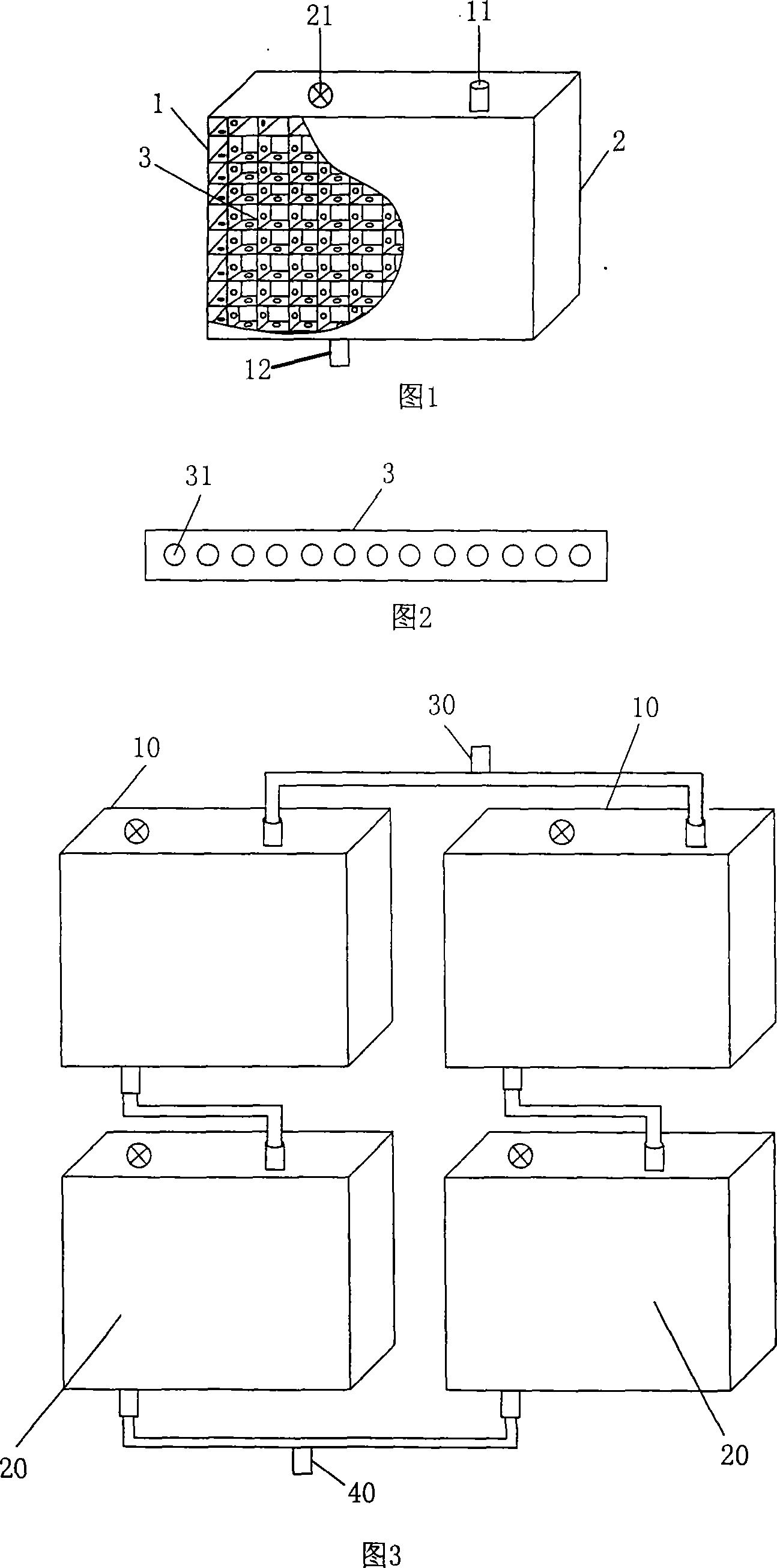
[0031] The vacuum flat panel solar heat collector of this embodiment is a structure of a single heat collector, as shown in Figure 1, it is composed of two flat inner boxes 1 and outer boxes 2 that are nested together. The square grid network formed by grid rib sheet 3 is used to connect between them. The grid rib sheet 3 is provided with a round through hole 31, so that the gap between the two boxes is connected. As shown in Figure 2, a box is set on the upper end of the outer box body. The valve 21 that can be vacuumed, through the vacuum valve, the air between the two boxes is drawn out to form a vacuum layer; the upper and lower end faces of the box are respectively provided with outlet pipe interfaces 11 and Water inlet pipe interface 12; the front panel of the outer box is made of plexiglass transparent plate, the side panels, upper and lower end panels and the rear panel are all opaque plastic plates, and each panel of the inner box is made of stainless steel. The outer...

Embodiment 2

[0036] The vacuum flat panel solar heat collector of this embodiment is a combined structure of 4 boxes, as shown in Figure 3, the structure of each box of this embodiment is the same as that of Example 1, except that the two boxes in the upper row The water inlet pipe interface of the box body 10 is connected with the water outlet pipe interfaces of the two box bodies 20 in the lower row, and the water outlet pipe interfaces of the two box bodies 10 in the upper row are connected to form a total water outlet pipe interface 30; The water inlet pipe interfaces of the box body 20 are connected to form a general water inlet pipe interface 40; forming a collector plate array.

[0037] The size of the outer box of each heat collector of the present embodiment is about 1200 mm in length, about 1000 mm in height, and about 100 mm in thickness.

[0038] The size of the inner box is about 1180 mm in length, about 980 mm in height, and about 80 mm in thickness.

[0039] The gap between...


PUM


Abstract

The invention relates to a vacuum flat plate solar energy heat collecting device belonging to the technical field of solar energy application. The device is a flat plate heat collecting device consisting of a flat inner box body and a flat outer box body which are coated together. The inner box body and the outer box body of the heat collecting device are respectively connected by a bar rib meshwork. The bar rib meshwork is provided with a through hole. One end of the outer box body is provided with a vacuum valve. The upper and lower end surfaces of the heat collecting device are respectively provided with a water outlet tube interface and a water inlet tube interface directly through to the inner box body. The front panel of the outer box body is a transparent plate material. The external surface of the panel corresponding to the inner box body is coated with a gradually changed aluminum nitrogen aluminum membrane. The invention also includes a flat plate heat collecting device array consisting of a plurality of heat collecting devices. The invention has the advantages of high thermal efficiency, good anti-freezing performance, no crack and low cost. The invention can realize separation of heat collecting and heat storage. The invention can be hung on a wall, thus increasing the security.

Description

technical field [0001] The invention belongs to the technical field of solar energy applications, in particular to the structural design of solar heat collecting devices Background technique [0002] Solar collectors are the main components of solar water heaters. It mainly uses water as the carrier to convert solar energy into heat energy, so as to realize the application of solar water heaters. [0003] In the early stages of solar collectors, people simply used an iron bucket, painted the surface black, and filled it with water. Such facilities have low thermal efficiency and cannot be kept warm. Despite this, due to the low price, even users can do it themselves, so it is still in use. [0004] The first generation of solar collectors is a flat plate, which separates heat collection from water storage, and the water storage tank is insulated. The hot water is sent to the storage tank through the heat collecting plate. But this device has several problems: A. It cann...

Claims


Application Information

Patent Timeline
Patent Type & Authority Applications(China)
IPC IPC(8): F24J2/05F24J2/20F24J2/46F24S10/40F24S10/50
CPCY02E10/44
Inventor 夏靖友
Owner 北京九艺通文化艺术有限公司
Why Eureka
Try Eureka