
Novel pipe throttling device

A throttling device and tube-type technology, which is applied in fluid circulation arrangement, high-efficiency regulation technology, lighting and heating equipment, etc., can solve problems such as poor matching of refrigerants and inability to adjust the refrigerant circulation area

Inactive Publication Date: 2008-06-18
TIANJIN UNIVERSITY OF SCIENCE AND TECHNOLOGY
View PDF0 Cites 0 Cited by
  • Summary
  • Abstract
  • Description
  • Claims
  • Application Information

AI Technical Summary

Problems solved by technology

However, the throttling device currently used is an integral rigid tube. After it is installed in refrigeration, air conditioning, and heat pump systems, its length and diameter are fixed, and the flow area of ​​the refrigerant cannot be adjusted.
When the ambient temperature changes, the cooling or heating temperature changes, and the cooling capacity or heating capacity changes, the matching between the flow rate of the refrigerant through the throttling device and the air delivery capacity of the compressor is poor, and it is difficult to keep the cooling, air conditioning, and heat pump systems in good condition. run under optimal conditions

Method used


Image

  • Novel pipe throttling device
  • Novel pipe throttling device

Examples


Embodiment Construction

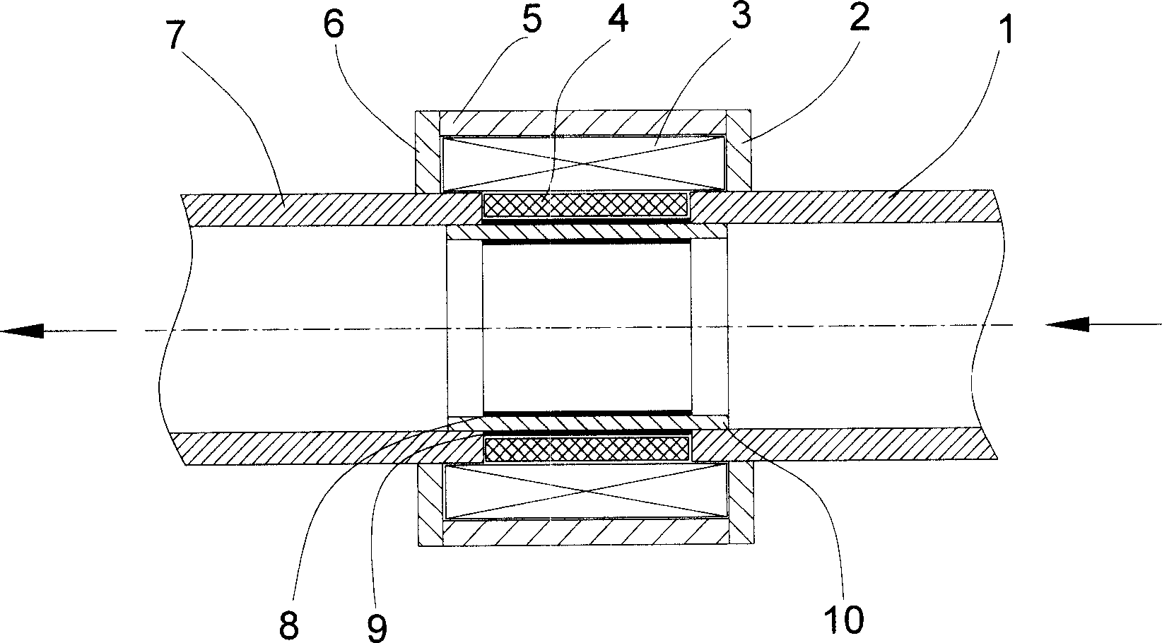
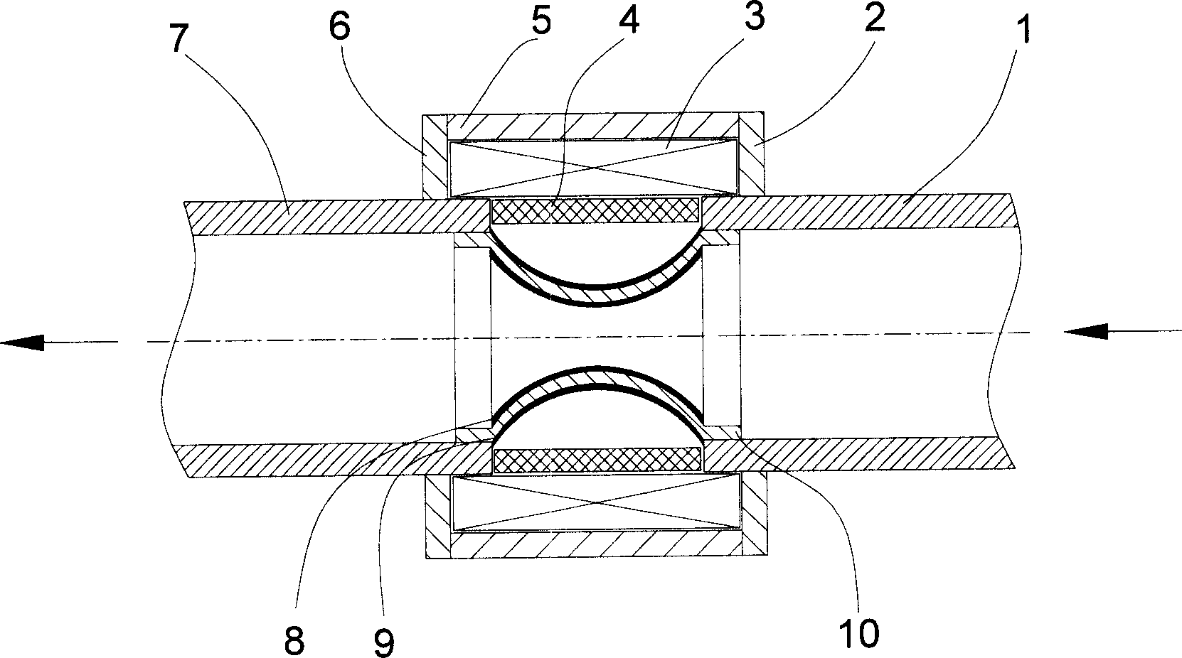
[0014] The liquid refrigerant enters the tube throttling device from the inlet pipe section 1. When refrigeration, air conditioning, and heat pump systems require a large refrigerant flow rate, the coil 3 of the tubular throttling device does not pass current, and the middle pipe section of the tubular throttling device is in the figure 1 In the state shown in , the flow area of ​​the refrigerant is the largest at this time. When the operating conditions of the refrigeration, air conditioning, and heat pump systems change, and the flow rate of the refrigerant needs to be adjusted to a small value, a current is passed through the coil 3 to generate a magnetic field. The positive magnetostrictive material 8 on the inner surface of the intermediate pipe section is axially elongated under the action of the magnetic field, the negative magnetostrictive material 9 on the outer surface of the intermediate pipe section is axially shortened under the action of the magnetic field, and t...


PUM


Abstract

The invention relates to a novel pipe throttling device for refrigerating, air conditioning and heat pump systems. The invention is to improve the control of the pipe throttling device to the refrigerant flow. The pipe throttling device of the invention leads in a middle pipe section consisting of positive magnetostrictive material (8), supporting material (10) and negative magnetostrictive material (9) between an inlet pipe section (1) and an outlet pipe section (2). When current is passed into a coil (3), a magnetic filed is generated; under the effect of the magnetic field, the positive magnetostrictive material (8) is extended and the negative magnetostrictive material (9) is shortened, so that the pipe wall of the middle pipe section bends to the center of the pipe and the circulation area of the refrigerant is reduced. When the current in the coil (3) is changed, the bending degree of the pipe wall of the middle pipe section is also changed, so as to flexibly control the flow when the refrigerant goes through the pipe throttling device.

Description

technical field [0001] The invention relates to a pipe throttling device for refrigeration, air conditioning and heat pump systems. The flow rate of refrigerant to the evaporator may be controlled according to the temperature of the refrigerant. Background technique [0002] The basic components of mechanical compression refrigeration, air conditioning, and heat pump systems are compressors, condensers, throttling devices, and evaporators. Refrigerant evaporates, gasifies and refrigerates under low pressure in the evaporator. The refrigerant vapor is boosted by the compressor and transported to the condenser. It releases heat, condenses and liquefies under high pressure in the condenser. The liquid refrigerant enters the evaporator after being decompressed by the throttling device. for the next cycle. [0003] The function of the throttling device is to control the flow of refrigerant flowing from the condenser to the evaporator, so that the refrigerant flow that the conde...

Claims


Application Information

Patent Timeline
Patent Type & Authority Applications(China)
IPC IPC(8): F25B41/06
CPCF25B2341/065F25B41/06Y02B30/72Y02B30/70F25B41/34
Inventor 谢继红陈东
Owner TIANJIN UNIVERSITY OF SCIENCE AND TECHNOLOGY
Learn More