
Automatically tracking device for direction rotating shaft fixed solar receiver

An automatic tracking device and receiver technology, applied in solar thermal devices, solar collectors, solar collector controllers, etc., can solve the problems of high production cost, high tracking energy consumption, complex structure, etc. Reduced complexity, low tracking energy consumption, and accurate tracking results

Active Publication Date: 2008-06-18
ANHUI TIANZHU GREEN ENERGY SCI & TECH
View PDF0 Cites 1 Cited by
  • Summary
  • Abstract
  • Description
  • Claims
  • Application Information

AI Technical Summary

Problems solved by technology

[0002] When using solar collectors to collect solar energy, the relative movement of the earth and the sun will cause the sunlight to irradiate the solar collectors obliquely, resulting in low collection efficiency. In order to ensure that the solar collectors can always face the sun, some tracking methods are currently used Device to drive the solar collector to follow the sun to achieve synchronous tracking of the sun
An existing class of ideal tracking devices can realize synchronous tracking in both azimuth and elevation angles, but there are problems such as complex structure, high manufacturing cost, high tracking energy consumption, and low reliability.

Method used


Image

  • Automatically tracking device for direction rotating shaft fixed solar receiver
  • Automatically tracking device for direction rotating shaft fixed solar receiver

Examples


Embodiment Construction

[0013] The present invention is further described below in conjunction with embodiment and accompanying drawing.

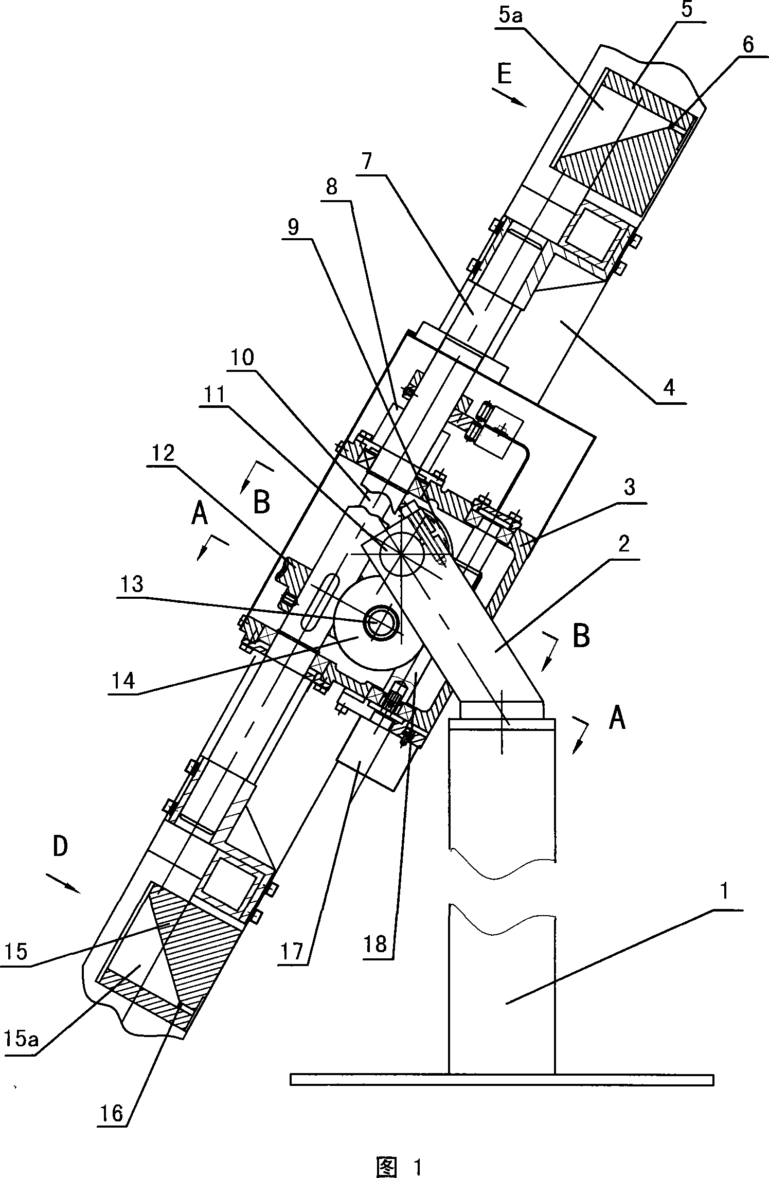
[0014] Referring to Fig. 1, the azimuth rotating shaft fixed solar receiver automatic tracking device provided by the present invention has a base 1, a support 2 is supported on the base 1, a light receiver 4 is connected to the support 2, and an elevation angle is fixed on the support 2 Shaft 11, a casing 3 is housed on the elevation angle axis 11, and the azimuth rotating shaft 7 perpendicular to the elevation angle axis 11 is housed on the casing 3, and the optical receiver 4 is connected with the azimuth rotating shaft 7.

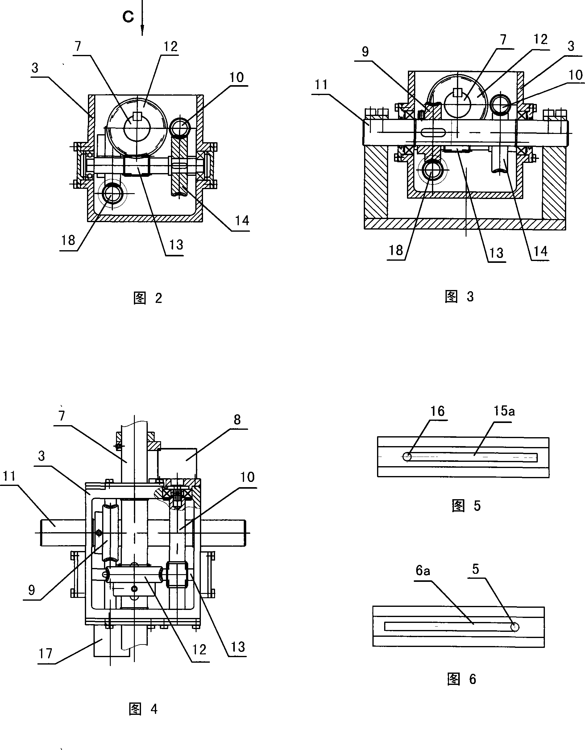
[0015] 1, FIG. 2, and FIG. 4, the casing 4 is provided with an azimuth transmission mechanism that rotates the azimuth shaft 7. A driving worm 10 and a driven worm 13 are mounted on the casing 4. The worm 13 is equipped with a worm wheel 14 meshing with the driving worm 10 , and a worm wheel 12 meshing with the driven worm 13 is fixed on th...


PUM


Abstract

The invention relates to an automatic tracking device for an azimuth rotary shaft to fix a solar receiver. A bracket (2) supported by a base body (1) is provided with an elevation shaft (11); a box body (3) on the elevation shaft is provided with an azimuth rotary shaft (7) vertical to the elevation shaft; an optical receiver (4) is linked with the azimuth rotary shaft; the box body is provided with an azimuth motor (8), an azimuth drive mechanism, an elevation motor (13) and an elevation drive mechanism; the optical receiver is provided with two light-collecting bases (5, 15) respectively with a light-collecting window; the upper surfaces of the two light-collecting bases are respectively provided with a groove (5a, 15a); the grooves respectively have an oblique surface; the light-collecting surface of the optical receiver is oblique; the two oblique surfaces of the two grooves are opposite in the slanting directions; the bottoms of the oblique surfaces of either groove are respectively provided with a photosensitive element (6,16). The tracking device is controlled by an electronic control device; thus the optical receiver is guaranteed to be always dead against the sun; the tracking device has a reasonable and reliable structure and accurate tracking; moreover, the tracking device can track other light sources.

Description

technical field [0001] The invention relates to a tracking device, in particular to a sun tracking device for a solar receiver. Background technique [0002] When using solar collectors to collect solar energy, the relative movement of the earth and the sun will cause the sunlight to irradiate the solar collectors obliquely, resulting in low collection efficiency. In order to ensure that the solar collectors can always face the sun, some tracking methods are currently used The device is used to drive the solar collector to follow the sun to realize synchronous tracking of the sun. An existing ideal tracking device can realize synchronous tracking in azimuth and elevation, but there are problems such as complex structure, high manufacturing cost, high tracking energy consumption, and low reliability. Contents of the invention [0003] The object of the present invention is to provide an automatic tracking device for a solar receiver with a fixed azimuth rotating shaft and ...

Claims


Application Information

Patent Timeline
Patent Type & Authority Applications(China)
IPC IPC(8): G05D3/00F24J2/38H02N6/00F24S50/20H02S20/32
CPCY02E10/47Y02E10/50
Inventor 卢育发李倩
Owner ANHUI TIANZHU GREEN ENERGY SCI & TECH
Learn More