[0029] Example 1:
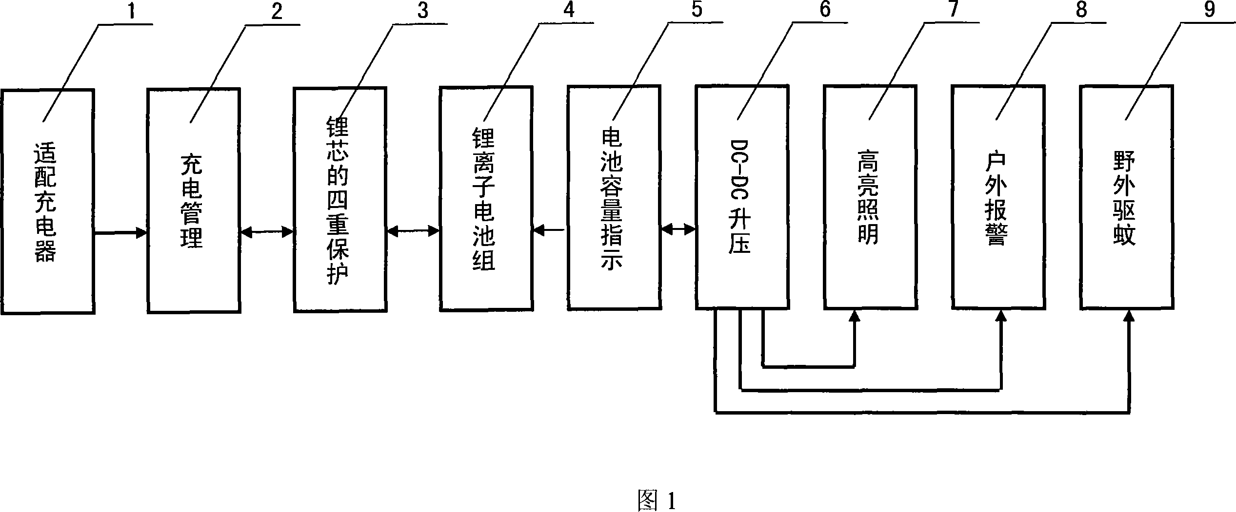
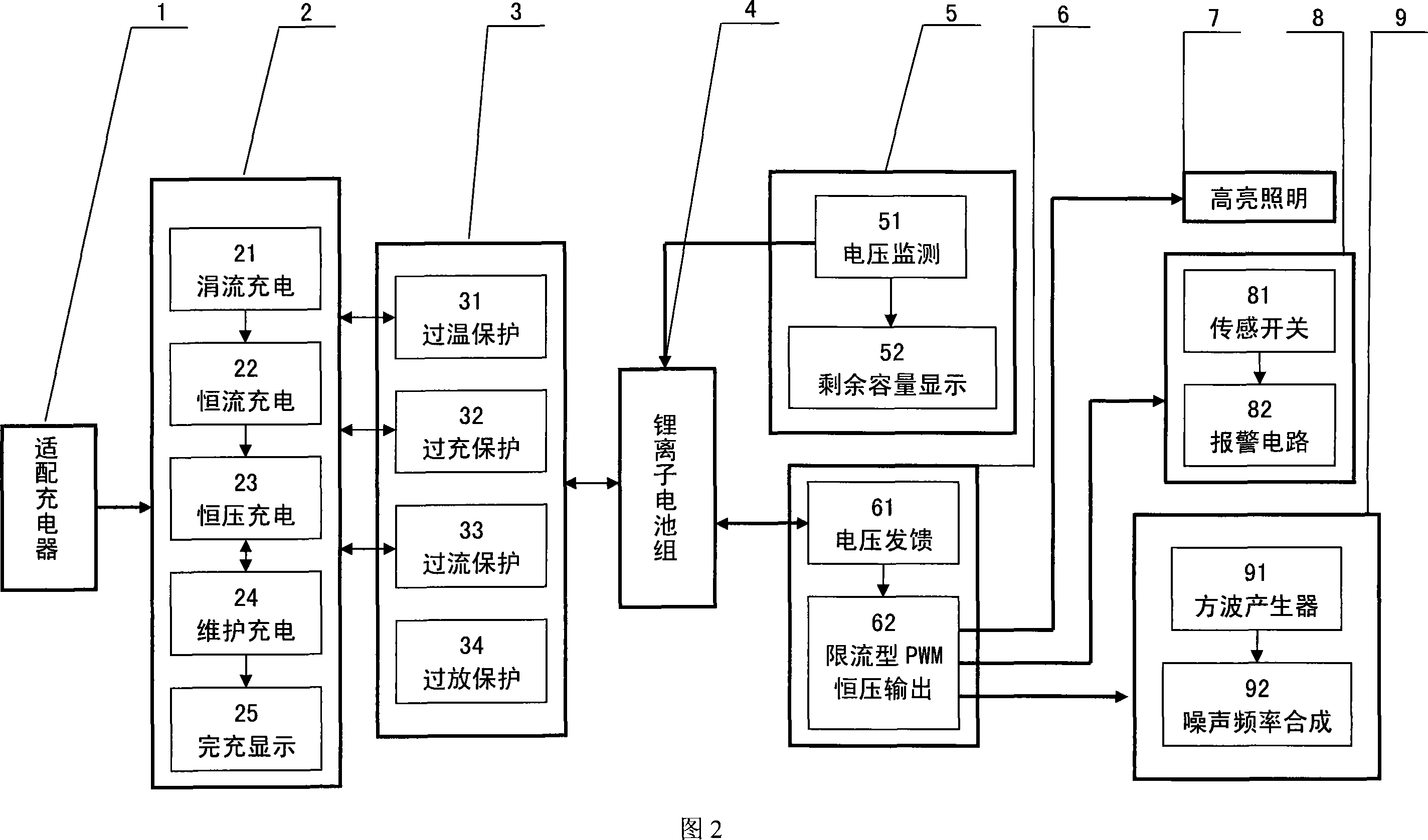
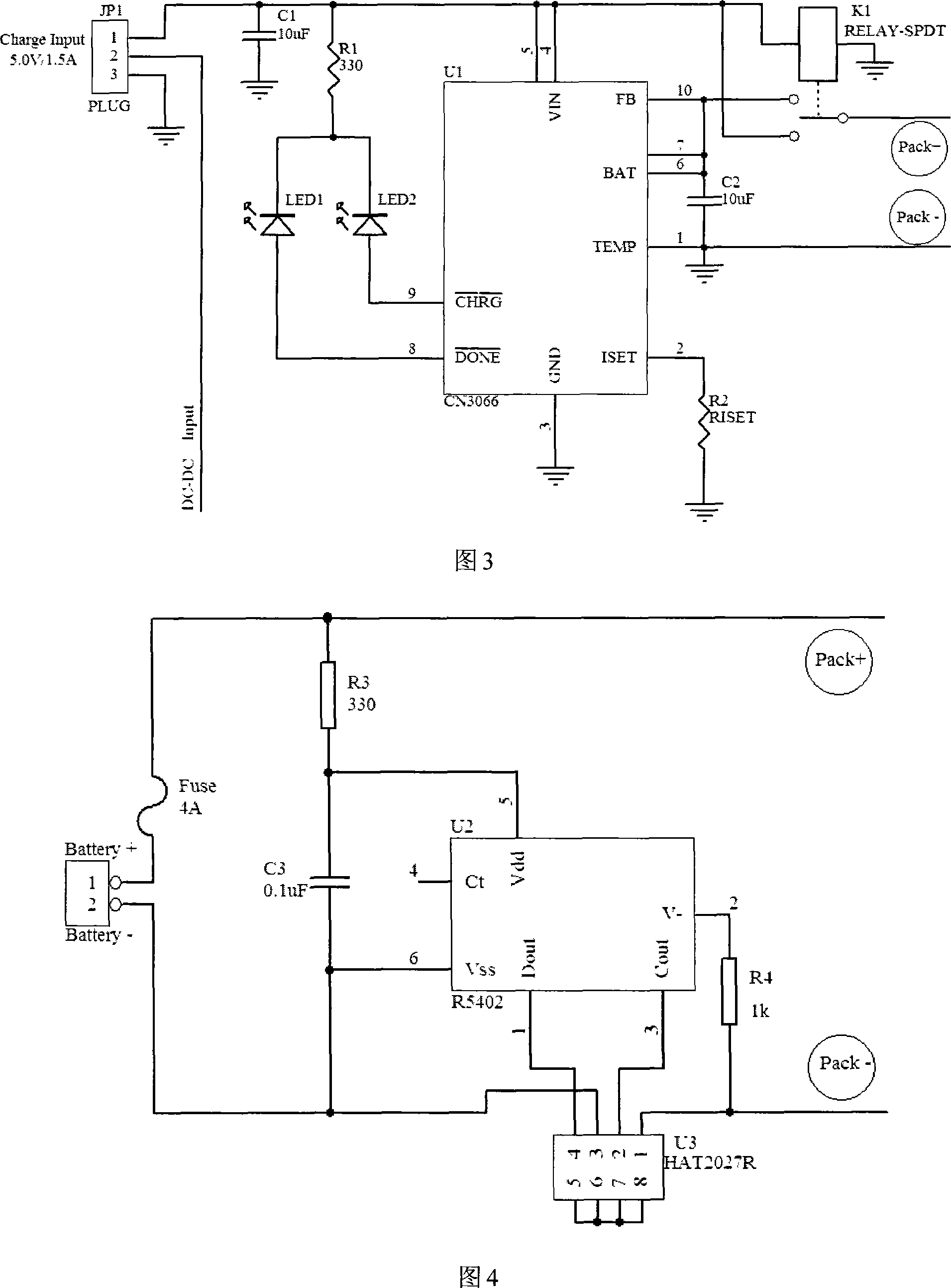
[0030] As shown in Figures 1 and 2, the multifunctional portable power supply provided by the present invention includes a rechargeable and dischargeable lithium-ion battery pack connected in parallel, and the lithium-ion battery pack is sequentially connected to a lithium-core quadruple protection circuit and a charging management circuit through a wire; The lithium-ion battery pack is connected to the battery capacity indicator circuit through a wire at the same time; when charging, the adapter charger is connected to the charging management circuit to charge the lithium-ion battery pack connected to the lithium-core quadruple protection circuit; the lithium-ion battery pack is discharged After the DC-DC conversion circuit, it discharges the peripheral electronic equipment, and at the same time supplies power to the multifunctional expansion circuit through the DC-DC conversion circuit. The multi-function expansion circuit includes lighting circuit, mosquito repellent circuit, and alarm circuit. The specific connection circuit is shown in Figure 3 to Figure 8.
[0031] The DC-DC Input in Figure 3 is connected to the DC-DC Input in Figure 6; the Pack+ in Figure 3 is connected to the Pack+ in Figure 4, the Pack+ in Figure 5, and the Pack+ in Figure 6; the Pack- in Figure 3 Connect to Pack- in Figure 4, Pack- in Figure 5, and Pack- in Figure 6; Output+ and Output- in Figure 6 are connected to Output+ and Output- in Figure 7 and Output+ and Output in Figure 8 respectively -; Battery+ and Battery- in Figure 4 are respectively connected to the positive and negative poles of two parallel lithium cores. As shown in Figure 3, the charging management circuit includes: a management chip (U1), the management chip (U1) end, The terminals are respectively connected to the driving terminal of the relay (K1) through the first resistor (R1) after the first light-emitting diode (LED1) and the second light-emitting diode (LED2) connected in the forward direction. The first resistor (R1) and the first capacitor ( C1) are connected to the VIN terminal of the management chip (U1), the second capacitor (C2) is connected between the BAT terminal and TEMP terminal of the management chip (U1), and the FB terminal and BAT terminal of the management chip (U1) are connected to the relay at the same time The normally open terminal of (K1), the normally closed terminal of the relay (K1) is connected to the VIN terminal of the management chip (U1), the common terminal of the relay (K1) and the TEMP terminal of the management chip (U1) are respectively connected to the protection circuit PACK+ terminal, PACK- terminal. JP1 in Figure 3 is the charging input port. When the charging plug is inserted, ports 1 and 2 of JP1 are separated from the closed state, disconnecting the DC-DC boost circuit, the charging management circuit, and the lithium core protection circuit. 1 of JP1 Input 5V/1.5A into the port, and the relay K1 is working in the closed state. CN3066 starts to enter the charging management stage. According to the voltage and current at both ends of the Pack+ and Pack-, it adjusts the charging voltage and charging current, and selects the appropriate charging mode. Monitor the temperature and charging time to maximize the charging capacity of the lithium core within a safe range. After the full charge is over, the red light LED1 is off and the green light LED2 is on.
[0032] The lithium-core quadruple protection circuit shown in Figure 4 includes overcharge, overdischarge, overcurrent, and overtemperature protection. The composition of the protection circuit includes: a management chip (U1), a protection chip (U2), and a dual MOS field effect transistor (U3). ; The third capacitor (C3) is connected to the Vdd end and the Vss end of the protection chip (U2), the lithium-ion battery pack is connected to the self-recovery fuse (Fuse), and is connected to the protection chip (U2) through the third resistor (R3) One end of Vdd; when the temperature of the lithium-ion battery pack reaches 60°C, the management chip (U1) shuts off the connection between the management circuit and the lithium-ion battery pack. When R5402 detects that the voltage of the lithium-cell battery pack is higher than 4.25V, Hat2027 conducts unidirectionally, and the current flows from pin 1 to pin 3, and the charging state is latched to prevent the lithium cell from overcharging; when the voltage of the lithium-cell battery pack is monitored When it is lower than 2.3V, Hat2027 conducts unidirectionally, and the current flows from pin 3 to pin 1, and the discharge state is latched to prevent over-discharge of the lithium core. Self-recovery fuse prevents excessive load current or short circuit.
[0033] The structure of the battery capacity indicator circuit in Figure 5 includes four voltage detection chips (U4 ~ U7), and the third to sixth light-emitting diodes (LED3 ~ LED6) are connected in parallel between the VOUT terminal and the VSS terminal of the voltage detection chip. After a branch composed of one and one of the fifth to eighth resistors (R5 to R8), the VIN terminal and the VSS terminal of the voltage detection chip are connected between the positive and negative electrodes of the battery pack. When the Q1 button is pressed, the capacity of the lithium-cell battery pack can be monitored.
[0034] The composition of the DC-DC conversion circuit in Figure 6 includes a boost chip (U8), an inductor (L), an NMOS field effect tube (U9), a Schottky diode (D1) and a ninth to eleventh resistor (R9). ~R11), the fourth to eighth capacitors (C4~C8)) constitute the circuit network composition; the external FET gate drive end of the boost chip (U8) is connected to the gate of the NMOS FET (U9) , One end of the ninth resistor (R9) is connected to the voltage feedback output terminal of the boost chip (U2), and at the same time connected to the source of the NMOS FET (U9), the drain of the NMOS FET (U9) and the inductor (L) Connect in series with Schottky diode (D1) at the same time; connect the tenth and eleventh feedback resistors (R10~R11) in series between the high voltage end and the low voltage end of the constant voltage output, the eleventh The feedback voltage obtained by the feedback resistor (R11) is connected to the feedback input of the boost chip (U8); under the action of the boost chip (U8), inductor (L) and NMOS field effect transistor (U9), linear PWM pulses are generated Square wave, control the NMOS field effect transistor (U9) to turn on or off. The vibration frequency of the pulse square wave is related to the feedback voltage of the eleventh feedback resistor (R11) to the boost chip (U2); the AC current output by the inductor passes through the The rectification and filtering of the special-key diode (D1), the sixth and eighth capacitors (C6, C8) obtain a direct current.
[0035] The DC-DC boost circuit adopts an improved current-limiting PFM control method, which uses the SEPIC topology to control the on or off of the MOS tube IRF7457 in the circuit to store or release the inductor voltage. This not only maintains the low quiescent current of the traditional PFM, but also has high efficiency under heavier loads, and because the peak current is limited, a small volume of external components can be used to obtain a satisfactory output ripple, thus reducing Circuit cost and circuit size.
[0036] The lighting, alarm, and mosquito repellent circuits shown in Figures 7 and 8 are practical, safe and convenient, so that the portable power supply can play a greater role in outdoor activities. Press Switch1 to make the portable power supply work in the pre-warning state. When the Mercury Swtich (mercury switch) deviates from the normal position, the alarm circuit starts to work and an alarm sounds; when Switch2 is pressed, the two high-bright lamps LED7 and LED8 are in the current limiting resistor. It emits light under the protection of R14; Switch3 is pressed, the 555 circuit composed of U10 generates an oscillation frequency of 22kHz, and the 555 monostable circuit composed of U11 generates a 50Hz square wave with a duty cycle of 50% and inputs it to pin 5 of U10 to synthesize A type of noise used to repel mosquitoes.