Supercharge Your Innovation With Domain-Expert AI Agents!

Helicopter co-axis double rotator rotate speed differential device

A technology of coaxial dual rotors and differential rotation speed, applied in the field of helicopters, can solve the problems of differential rotation speed and complex structure of two rotors, and achieve the effect of reducing interference

Inactive Publication Date: 2010-05-12
郭正 +1
View PDF2 Cites 20 Cited by
  • Summary
  • Abstract
  • Description
  • Claims
  • Application Information

AI Technical Summary

Problems solved by technology

[0003] In order to avoid adding a differential variable pitch rod mechanism on the rotor shaft of a microcoaxial helicopter to cause an overly complicated structure, and to overcome the shortcomings that the existing dual-motor speed differential method cannot be used for non-electric helicopters or single-engine helicopters, the present invention provides A gear transmission device that distributes a single power input to the upper and lower rotors, and can realize the speed difference between the two rotors according to the needs, so as to realize the yaw control of the helicopter

Method used


Image

  • Helicopter co-axis double rotator rotate speed differential device
  • Helicopter co-axis double rotator rotate speed differential device
  • Helicopter co-axis double rotator rotate speed differential device

Examples


Embodiment Construction

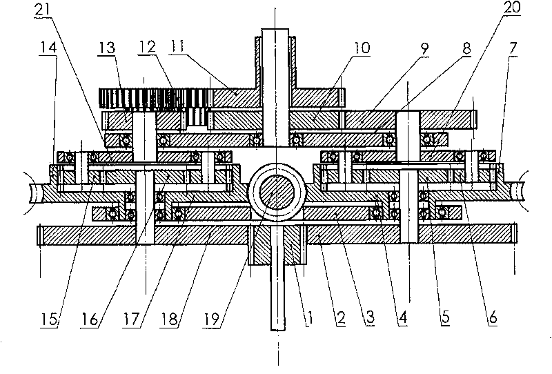
[0037] exist figure 2 In the schematic diagram of the longitudinal section structure, the parts below the upper support frame (8) are left-right symmetrical, and the power is divided into two strands, which drive the inner shaft and the outer shaft of the rotor respectively.

[0038] The power transmission route on the right is as follows: the power input gear (1) meshes with the first-stage reduction gear (2) on the right, and transmits the power to the first-stage reduction gear (2) on the right, which is the first-stage transmission; The stage reduction gear (2) is coaxially and rigidly connected with the right sun gear (5), and the right sun gear (5) meshes with the right planetary gear (6), and the right planetary gear (6) also engages with the right internal gear (7) meshing, when the speed differential is not performed, the right internal gear (7) is stationary, and the power is transmitted from the right primary reduction gear (2) to the right sun gear (5), and then d...


PUM


Abstract

The invention relates to a device for realizing rotor rotating speed differential of a coaxial helicopter with twin rotors which can be used for realizing the yawing control of the coaxial helicopterwith twin rotors. The device is a set of three-level gear drive mechanism: a first drive divides single power input into two parts according to the same drive ratio; a second drive is two planetary gear reducers with the same structure and the two parts of power after the first drive respectively drive sun wheels of the two planetary gear reducers; a third drive allows the output of the two planetary gear reducers to respectively drive a rotor internal shaft and a rotor external shaft according to the same drive ratio so as to realize that the rotary directions of the internal shaft and the external shaft is opposite. The key of realizing the rotating speed differential lies in drive configurations of the planetary gear reducer in the second lever, which has two structures: first, planetary wheel disks are used as the output and internal gears of the two planetary gear reducers can rotate and be catenated; second, the internal gears are used as the output and the planetary wheel disksof the two planetary gear reducers can rotate and be catenated. When two internal gears (the first configuration) or the two planetary wheel disks (the second configuration) are static, the rotor internal shaft and the rotor external shaft rotate at the same speed and in the opposite directions; when the two internal gears (the first configuration) or the two planetary wheel disks (the second configuration) rotate synchronously at the same speed driven by an execution mechanism for controlling the yawing, the rotating speed of the rotor internal shaft and the rotor external shaft increases anddecreases respectively and the increasing amount and the decreasing amount is the same.

Description

Technical field [0001] The invention belongs to the technical field of helicopters. Background technique [0002] There are two existing coaxial dual-rotor helicopter yaw control methods, one is realized by pitch differential, that is, the pitch of the upper and lower rotors is different through the pitch-variable rod mechanism (the pitch of the upper and lower rotors is increased by one). One is larger and the other is smaller), resulting in a torque difference, which drives the fuselage to rotate to achieve the purpose of yaw; the other is the dual-motor speed differential method, which is often used in small coaxial model helicopters. This method uses two motors to drive a pair of The rotor uses an electronic speed control circuit to control the speed of the two motors to realize the differential speed of the two rotors, thereby generating a torque difference and realizing yaw. The pitch differential method is mostly used in large-scale manned coaxial helicopters. Due to...

Claims


Application Information

Patent Timeline
Patent Type & Authority Patents(China)
IPC IPC(8): B64C27/10B64C27/14
Inventor 郭正
Owner 郭正
Features
  • R&D
  • Intellectual Property
  • Life Sciences
  • Materials
  • Tech Scout
  • Unparalleled Data Quality
  • Higher Quality Content
  • 60% Fewer Hallucinations
Learn More