Floating hydraulic system for end gate of pavement milling and planning machine

A floating hydraulic system and milling technology, which is applied in the hydraulic system and the hydraulic system of the tailgate of road milling machines, can solve the problems of reduced road surface pressing force, unadjustable road surface pressing force, and tailgate deformation, etc., to achieve The effect of reducing the pressure

Inactive Publication Date: 2008-06-25
ZHENJIANG HUACHEN HUATONG ROAD MASCH CO LTD
View PDF0 Cites 3 Cited by
  • Summary
  • Abstract
  • Description
  • Claims
  • Application Information

AI Technical Summary

Problems solved by technology

When the pressure of the tailgate on the road surface is high, the material collected on the road surface will be clean, but it will bring additional resistance to the forward movement of the milling machine, consume a lot of engine power, cause the tires to slip during the forward process, and even cause the tailgate to deform; When the pressing force of the tailgate on the road surface is small, although the forward resistance of the milling machine becomes smaller, the pressing force on the road surface decreases, resulting in unclean collection of materials on the road surface and increasing the cleaning workload
Existing road milling machines mainly rely on the weight of the tailgate to compress the road surface, and there is a defect that the pressure force of the tailgate on the road surface cannot be adjusted

Method used


Image

  • Floating hydraulic system for end gate of pavement milling and planning machine
  • Floating hydraulic system for end gate of pavement milling and planning machine

Examples


Embodiment Construction

[0014] The present invention will be further described below in conjunction with drawings and embodiments.

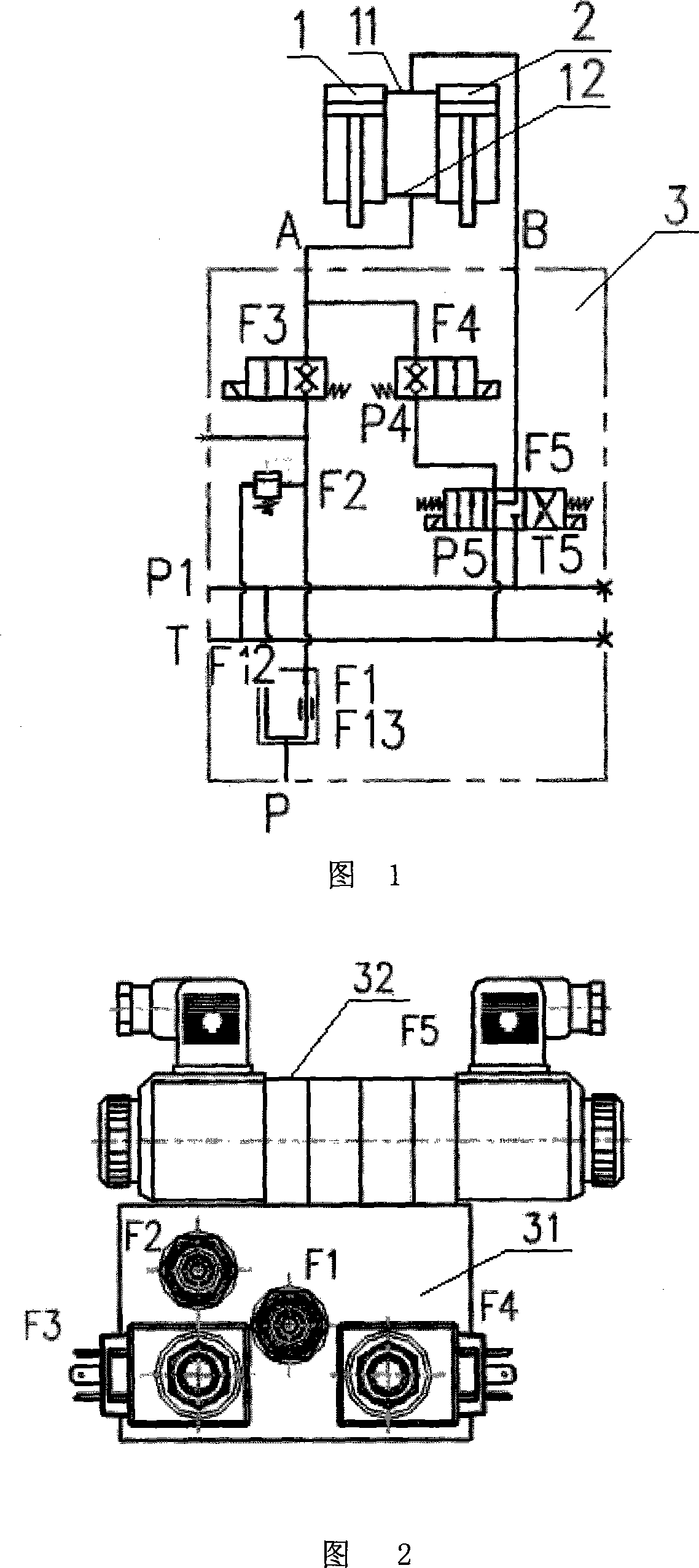
[0015] As shown in Figure 1, the present invention includes a priority speed regulating valve F1, an overflow valve F2, a first normally closed two-position solenoid valve F3, a second normally closed two-position solenoid valve F4, a three-position electromagnetic reversing valve F5, and a tailgate Lift cylinders 1 and 2. Due to the wide tailgate, double lifting cylinders 1 and 2 are used to lift the tailgate. The rodless chamber and the rod chamber of the tailgate lifting cylinders 1 and 2 are connected in parallel, and the high-pressure oil outlet of the system is connected to the priority speed control valve F1. The oil inlet P, the priority oil outlet F11 of the priority speed regulating valve F1 is connected to the oil inlet 6 of the relief valve F2 and the oil inlet P3 of the first normally closed two-position solenoid valve F3, and the priority oil outlet of the...


PUM


Abstract

The invention provides an end door floating hydraulic system of a pavement milling machine, which relates to a hydraulic system of the pavement milling and planning machine. The invention comprises a priority governor valve, an overflow valve, a first normal close two-position electromagnetic valve, a second normal close two-position electromagnetic valve, a three-position electromagnetic reversing clapper and an end door lift cylinder, wherein, a system high pressure oil outlet is connected with an oil inlet of the priority governor valve; a priority oil outlet of the priority governor valve is communicated with an oil inlet of the overflow valve, and communicated with an oil inlet of the first normal close two-position electromagnetic valve; a hydraulic fluid port of the three-position electromagnetic reversing clapper is communicated with an oil inlet of the second normal close two-position electromagnetic valve; an oil outlet of the second normal close two-position electromagnetic valve is connected with an oil outlet of the first normal close two-position electromagnetic valve, and then is communicated and connected with an oil conduit with a rod chamber of the end door lift cylinder via the hydraulic fluid port; the hydraulic fluid port of the three-position electromagnetic reversing clapper is communicated and connected with an oil conduit without rod chamber of the end door lift cylinder via the hydraulic fluid port. The invention fulfills simple structure, reliable performance, and aims of regulating the pressing force of the end door of the pavement milling machine to the pavement.

Description

technical field [0001] The invention relates to a hydraulic system of a road milling machine, in particular to a hydraulic system of a tailgate of a road milling machine, and belongs to the technical field of variable capacity machinery. Background technique [0002] During the milling operation, the road milling machine presses the road surface through the tailgate to ensure that the milled materials remain in the milling bin, and then transported to the truck by the belt conveyor for transport. When the pressure of the tailgate on the road surface is high, the material collected on the road surface will be clean, but it will bring additional resistance to the forward movement of the milling machine, consume a lot of engine power, cause the tires to slip during the forward process, and even cause the tailgate to deform; When the pressing force of the tailgate on the road surface is small, although the forward resistance of the milling machine becomes smaller, the pressing f...

Claims


Application Information

Patent Timeline
Patent Type & Authority Applications(China)
IPC IPC(8): F15B11/00F15B13/02E01C23/088
Inventor 王富春刘益民肖翀宇向彦亮
Owner ZHENJIANG HUACHEN HUATONG ROAD MASCH CO LTD
Why Eureka
Try Eureka