Fibrous mat fixing structure

a fixing structure and fibrous mat technology, applied in the direction of vehicular safety arrangments, pedestrian/occupant safety arrangements, other domestic objects, etc., can solve the problems of appearance design degradation and productivity reduction, and achieve the effects of improving bonding strength, improving bonding strength, and simplifying facilities

Inactive Publication Date: 2006-06-29
KASAI KOGYO CO LTD
View PDF5 Cites 3 Cited by
  • Summary
  • Abstract
  • Description
  • Claims
  • Application Information

AI Technical Summary

Benefits of technology

[0014] In the fibrous mat fixing structure in accordance with the present invention, the fibrous mat is welded and integrally attached to the resin molding by means of the flat weld surface and the V-groove provided as the weld portion when the fibrous mat is integrally combined by ultrasonic working, so that the V-groove can be easily formed with the sharp projecting thread formed on the pressing surface of the horn even if the pressing force is small and drive with a small-capacity cylinder suffices for pressing. Also, the effect of anchoring in the V-groove based on a phenomenon in which the fibers of the fibrous mat bite into the molten surface of the resin molding can be expected as well as the melding effect of ultrasonic welding. An improved bonding strength can be obtained from the strength of ultrasonic welding and the bonding strength based on the anchoring effect. Moreover, the amount of melt of the resin molding is limited to prevent occurrence of any considerable sinkmark, an irregularity defect or the like in the finished surface of the resin molding.
[0015] In the fibrous mat fixing structure in accordance with the present invention, as described above, the resin molding and the fibrous mat are welded and integrally attached to each other in the weld portion thereof by using the flat pressing surface of the ultrasonic horn, and a V-groove is formed in the flat weld surface by the sharp projecting thread formed on the pressing surface of the horn to forcibly cause the fibers of the fibrous mat to bite into the molten portion of the resin molding. A resulting anchoring member can be expected and an improved bonding strength can be obtained even by short-time welding.
[0016] Therefore, a lower pressing force applied to the ultrasonic force may suffice; a compact air cylinder can be used as a pressing machine for applying the pressing force to the ultrasonic horn; the facilities can be simplified; the welding time can be reduced to achieve an improvement in operability; and the external appearance of the product can be improved.

Problems solved by technology

This is a major cause of a reduction in productivity.
Further, another drawback of increasing the possibility of occurrence of a defect in appearance such as sinkmark or an irregularity defect in the interior trim 1 product surface to cause a degradation in terms of appearance design in the situation where the formation of deep recesses in the welded portion is required has also been pointed out.

Method used


Image

  • Fibrous mat fixing structure
  • Fibrous mat fixing structure
  • Fibrous mat fixing structure

Examples


Embodiment Construction

[0030] Embodiments of a fibrous mat fixing structure in accordance with the present invention will be described in detail with reference to the accompanying drawings.

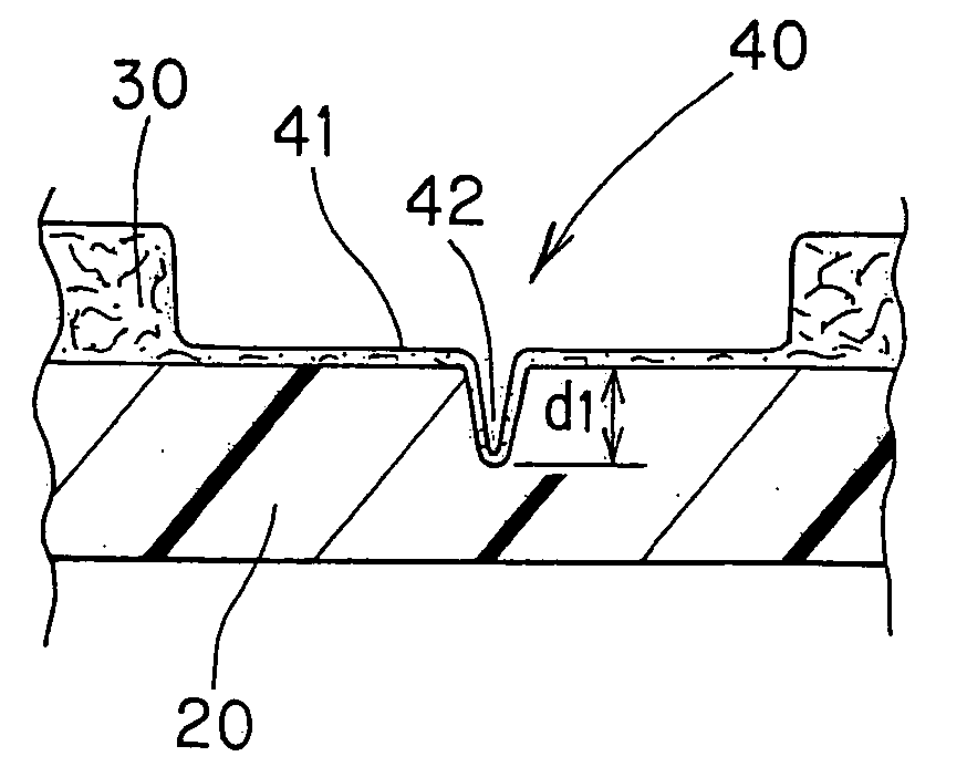
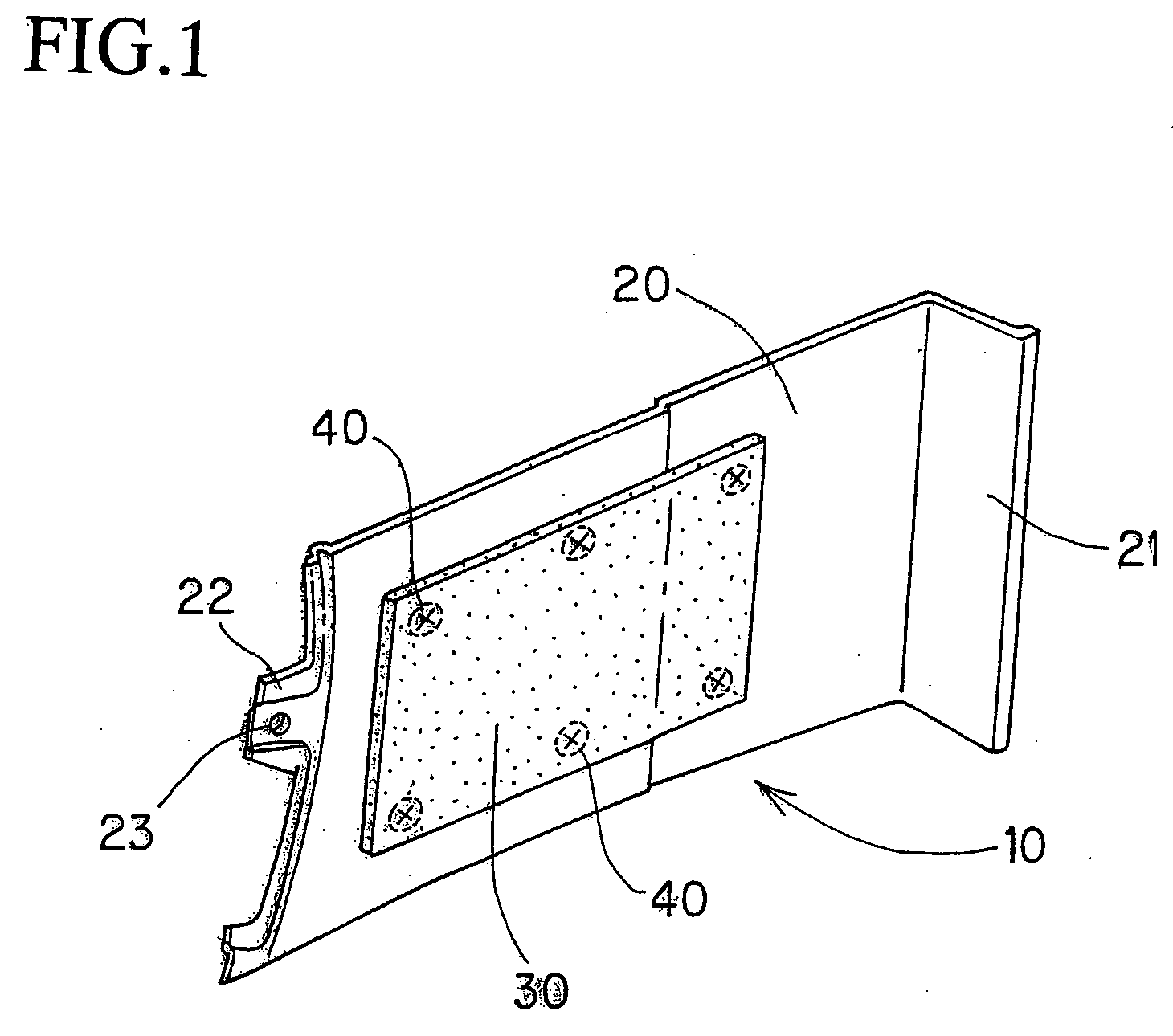
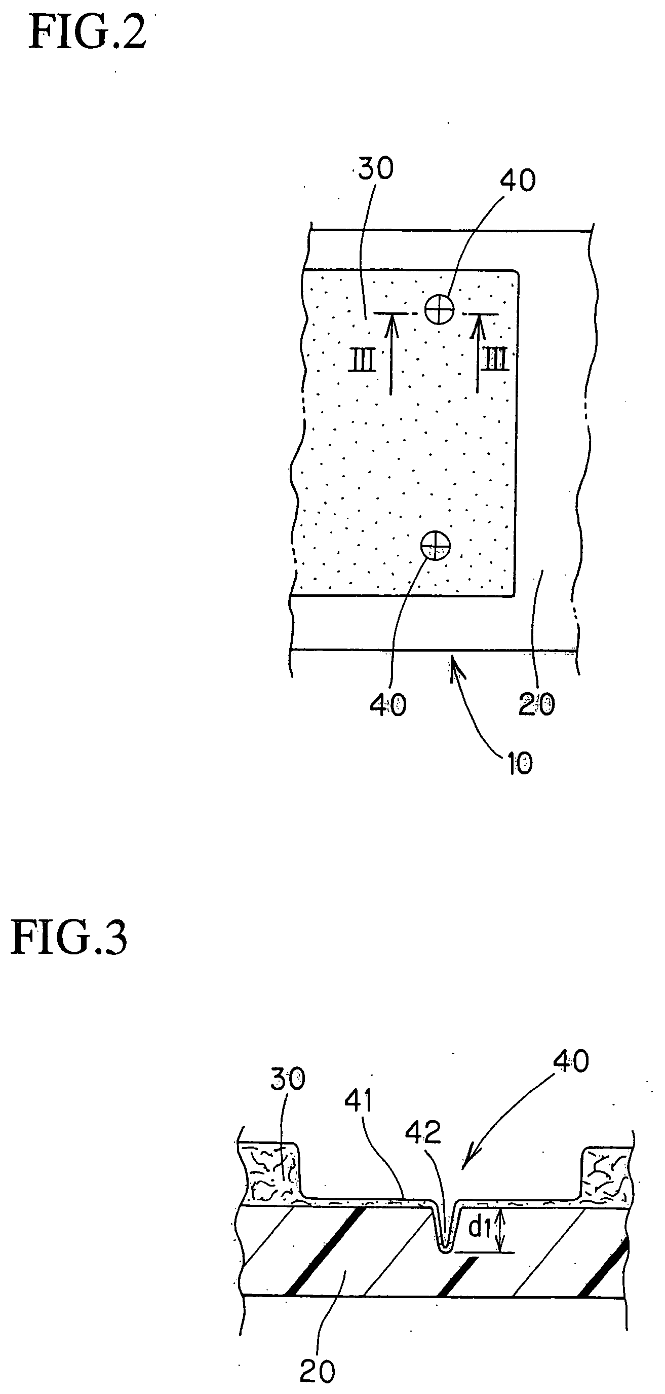
[0031] FIGS. 1 to 5 show a first embodiment of the present invention. FIG. 1 is a perspective view of a luggage room side trim seen from the back surface side, with a non-woven fabric mat attached to the back surface of the trim. FIG. 2 is a front view of the non-woven fabric mat attached to the luggage room side trim body. FIG. 3 is a cross-sectional view of a weld portion of the non-woven fabric mat. FIGS. 4(a) and 4(b) show the shape of an ultrasonic horn used in the first embodiment. FIG. 4(a) is a front view of the ultrasonic horn, and FIG. 4(b) is a view seen in the direction of arrow A in FIG. 4(a). FIG. 5 is a cross-sectional view showing a fibrous mat welding step using the ultrasonic horn shown in FIGS. 4(a) and 4(b). FIGS. 6 to 9 are diagrams showing examples of modifications of the first embodiment.

[0032] ...


PUM

PropertyMeasurementUnit
depthaaaaaaaaaa
depthaaaaaaaaaa
depthaaaaaaaaaa

Abstract

A fibrous mat fixing structure in which a fibrous mat such as a non-woven fabric mat 30 is integrally attached to a resin molding 20 by ultrasonic welding is designed to reduce the working time and simplify working facilities while preventing any considerable surface defect such as irregularities in the surface of the resin molding 20. A luggage room side trim (sound absorbing member for a vehicle) 10 has a fibrous mat such as a non-woven fabric mat 30 welded and integrally attached to a luggage room side trim main molding by an ultrasonic horn 50. A sharp projecting thread 52 is formed on a flat pressing surface 51 of the ultrasonic horn 50. A V-groove 42 which bites into the resin molding 20 is formed in a weld portion 40 of the non-woven fabric mat 30 together with a flat weld surface 41, thereby enabling fibers in the non-woven fabric mat 30 to easily bite into the molten surface of the resin molding 20. A resulting anchoring effect can be expected and the V-groove 42 can be formed in a short time in the resin molding 20, thus improving the operability while preventing occurrence of a defect in appearance.

Description

BACKGROUND OF THE INVENTION [0001] 1. Field of the Invention [0002] The present invention relates to a fibrous mat fixing structure and, more particularly, to a fibrous mat fixing structure capable of obtaining high bonding strength by welding in a short time when a fibrous mat is integrally attached by ultrasonic welding to a resin molding formed of a thermoplastic resin. [0003] 2. Description of the Related Art [0004] Interior trims comprising formed of resin moldings are ordinarily attached to interior side surfaces of vehicle molding panels by attachment means such as clips. A sound absorbing member is fixed on surfaces of such interior trims on the vehicle molding panel side to improve the quietness in the occupant compartment. For example, as shown in FIG. 12, a sound absorbing member 2 is fixed to the back surface of an interior trim 1 for a vehicle by bonding using an adhesive 3 to reduce the amount of noise propagating from the outside of the vehicle to the interior thereof...

Claims


Application Information

Patent Timeline
Patent Type & Authority Applications(United States)
IPC IPC(8): B32B3/00
CPCB29C65/08Y10T428/24612B29C66/303B29C66/80B29C66/81433B29C66/929B29C66/949B29K2105/0854B29L2031/3005B32B3/26B32B3/30B32B5/022B32B5/04B32B5/06B32B5/26B32B7/02B32B7/045B32B2250/02B32B2250/20B32B2262/0253B32B2262/0276B32B2262/06B32B2307/102B32B2307/51B32B2307/536B32B2605/003B32B2605/08B60R13/02B60R13/0256B60R21/2165B29C66/21B29C66/8322B29C66/81427B29C66/472B29C65/00B29C66/7392B29C66/71B29C66/73921B29C66/8167B29C66/1122B32B7/05B29K2067/00B29K2023/06B29K2023/12B29K2055/02
Inventor SASAKI, KEI
Owner KASAI KOGYO CO LTD
Why Eureka
Try Eureka