Extrusion Die for Metallic Material

a technology of extrusion die and metallic material, which is applied in the field of extrusion die, can solve the problems of increased size and weight but also an increased cost, insufficient die life, and deterioration of the dimensional accuracy of the extruded object, so as to reduce the pressing force, improve the strength of the pressing force of the metallic material, and ensure the effect of quality

Inactive Publication Date: 2007-12-13
SHOWA DENKO KK
View PDF5 Cites 3 Cited by
  • Summary
  • Abstract
  • Description
  • Claims
  • Application Information

AI Technical Summary

Benefits of technology

[0074] According to the extrusion die for metallic material as recited in the aforementioned Item [1], since the metallic material pressure receiving surface is formed into a convex configuration, when the metallic material is pressed against the pressure receiving surface, the pressing force of the metallic material can be received by being distributed by a convex surface, which in turn can reduce the pressing force at each portion of the pressure receiving surface in the direction of the normal line. Therefore, the strength to the pressing force of the metallic material can be improved, resulting in sufficient durability.
[0075] Furthermore, in this invention, since the porthole for introducing the material is formed in the dome portion of the die U holding case covering the male die and the female die, i.e., since the front end (downstream side) wall portion of the dome portion is integrally formed in the peripheral direction, the existence of this continued peripheral wall portion can markedly increase the strength of the die holding case, which in turn can further increase the entire strength of the extrusion die. Accordingly, in the die according to this invention, a portion weak in strength, such as, e.g., a conventional bridge portion, does not exist, and therefore it is not required to unnecessarily increase a size, such as, e.g., a thickness, to improve the strength, which makes it possible to attain the reduced size and weight and the cost reduction.
[0076] Furthermore, in this invention, since the porthole is formed in a periphery of the dome portion and the central axis of the porthole is inclined to the central axis of the die holding case so as to gradually approach the central axis of the die holding case toward the downstream side, the metallic material passing through the porthole can be stably extruded while being smoothly introduced to the axial center A1, i.e., the extrusion hole. Therefore, extrusion molding can be performed in a stable manner, which enables to obtain a high quality extruded member.
[0077] According to the extrusion die for metallic material as recited in the aforementioned Item [2], since the metallic material pressure receiving surface is constituted by the convex spherical surface, the pressing force of the metallic material to the pressure receiving surface can be distributed in a well-balanced manner, which makes it possible to improve the strength to the metallic material.
[0078] According to the extrusion die for metallic material as recited in the aforementioned Item [3], since the metallic material pressure receiving surface is constituted by the specific convex spherical surface, the pressing force of the metallic material to the pressure receiving surface can be assuredly distributed in a well-balanced manner, which makes it possible to assuredly improve the strength to the metallic material.
[0079] According to the extrusion die for metallic material as recited in the aforementioned Item [4], since a plurality of portholes are formed in the peripheral direction, the metallic material can be uniformly introduced from the periphery into the die holding case, resulting in smooth supplying of the metallic material to the extrusion hole, thereby enabling a more steady extrusion.

Problems solved by technology

In such an extrusion die, since a large stress due to the pressing of the metal billet is applied to the billet pressure receiving surface 1b of the male die 1, the stress may cause a generation of cracks in the billet pressure receiving surface and therearound, which in turn may result in insufficient die life.
Therefore, in order to secure sufficient strength of the bridge portion, the size of the male die such as the thickness of the bridge portion has to be increased beyond necessity, which results in not only an increased size and weight but also an increased cost.
This prevents smooth introduction of the metallic material, causing deteriorated dimensional accuracy of the extruded article, which in turn makes it difficult to attain high quality.

Method used


Image

  • Extrusion Die for Metallic Material
  • Extrusion Die for Metallic Material
  • Extrusion Die for Metallic Material

Examples


example 1

[0177] As shown in Table 1, in accordance with the aforementioned embodiment, an extrusion die having two portholes 24 and 24 and an 8° inclination angle θ of the central axis A2 of the porthole 24 to the central axis A1 was prepared.

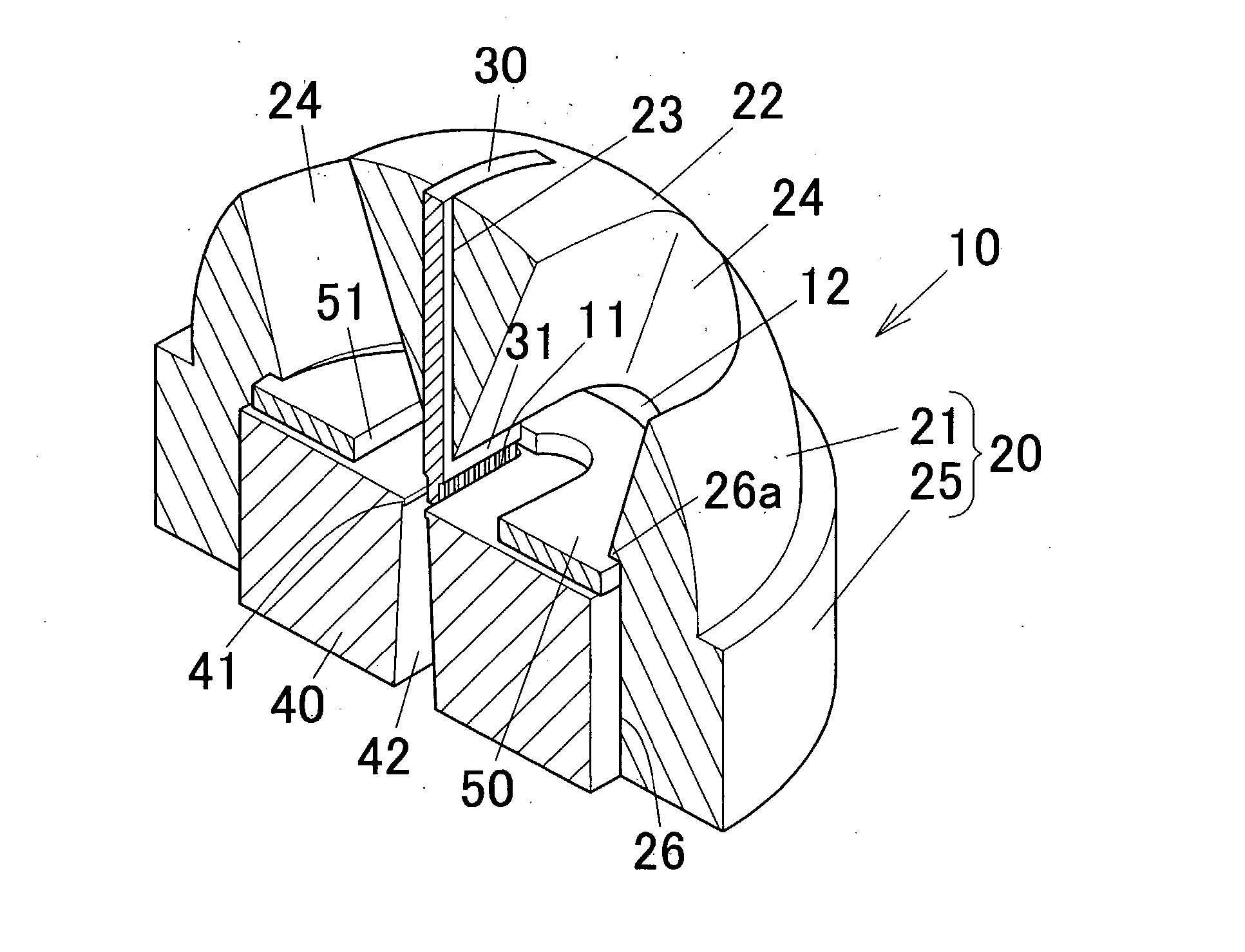
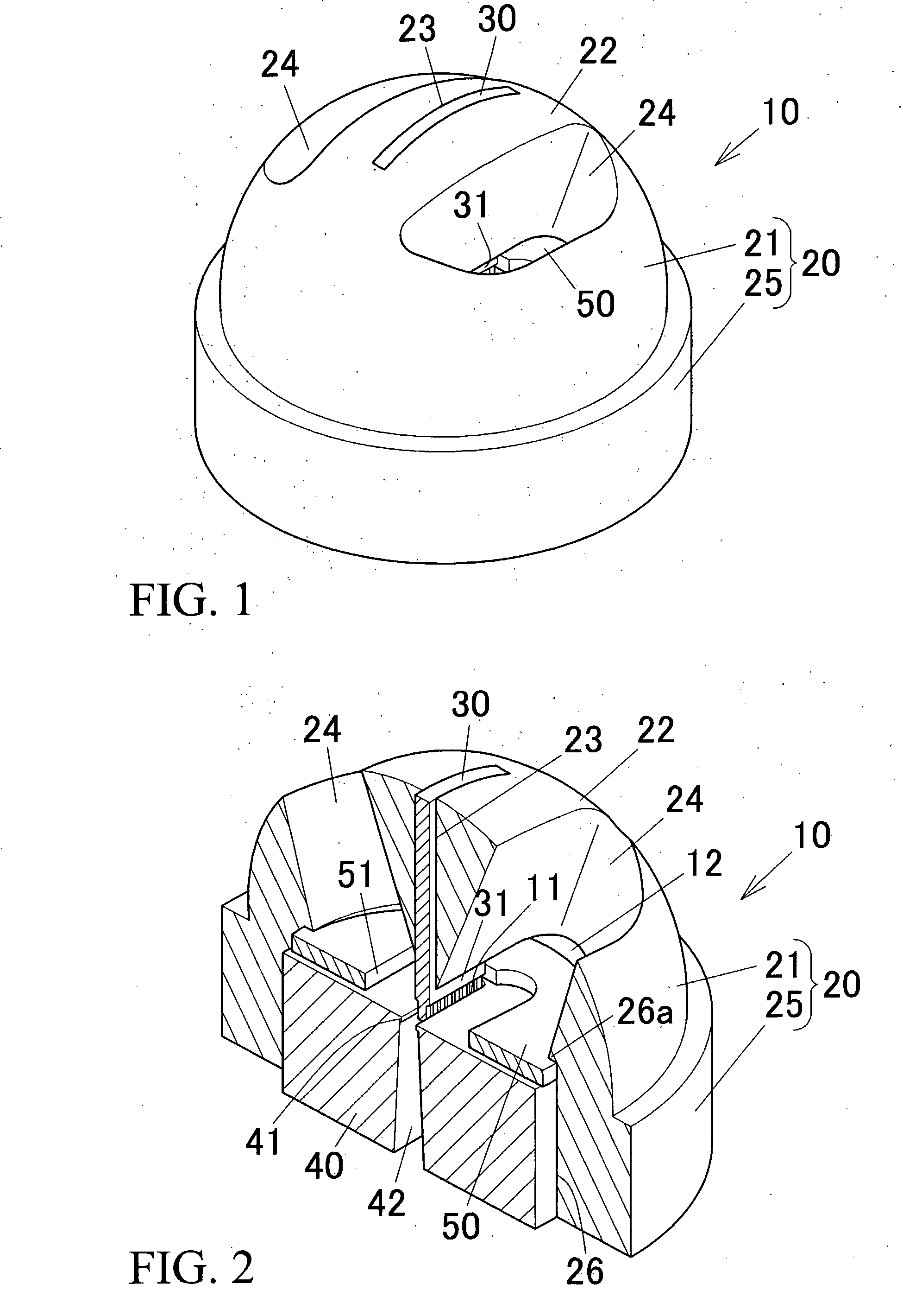
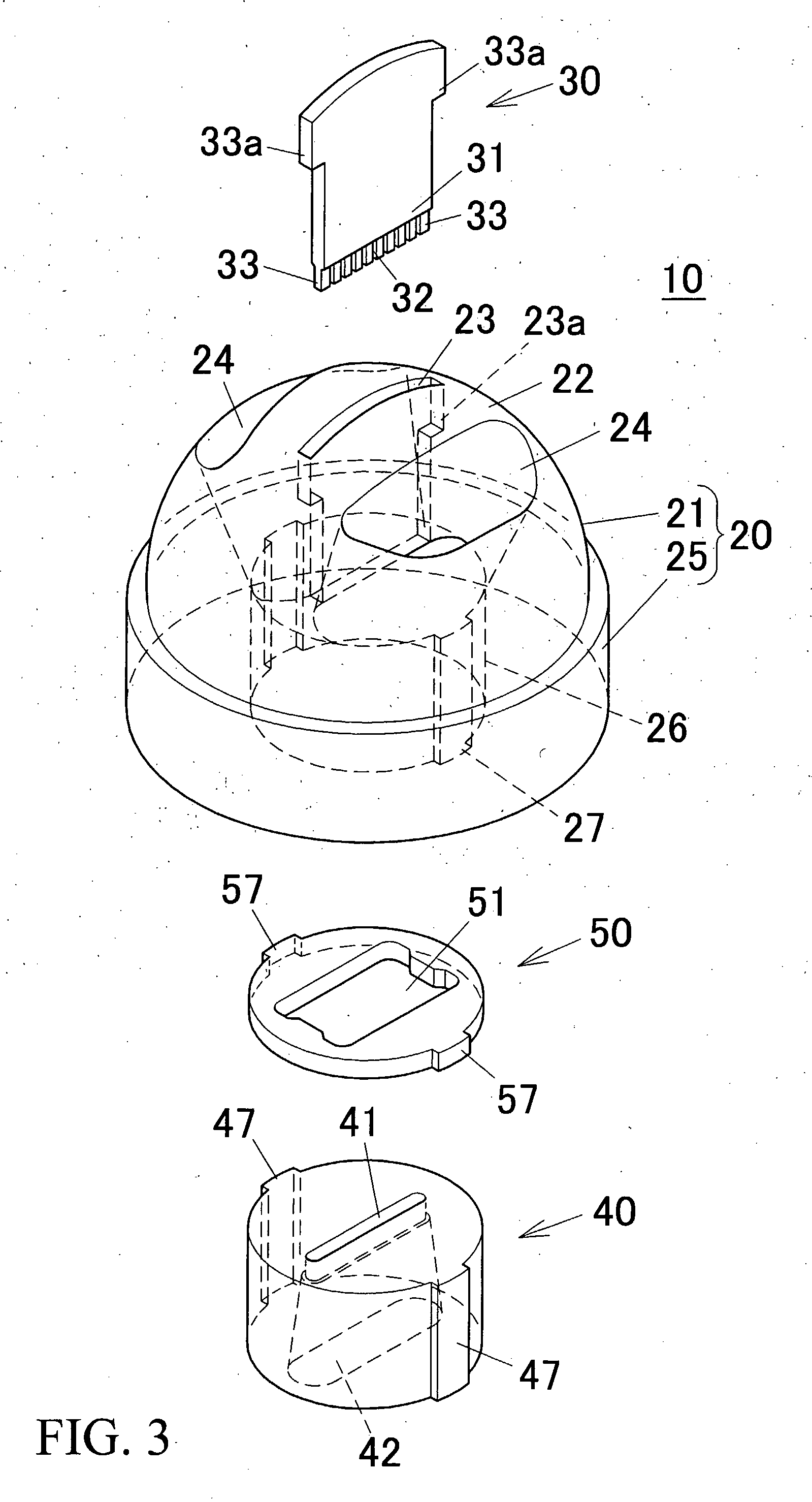
[0178] In this extrusion die, the billet pressure receiving surface 22 was constituted by an external periphery of a ½ sphere of radius 30 mm. As a male die 30, a male die in which the height (thickness) of the mandrel 31 was 2.0 mm, the width of the mandrel 31 was 19. 2 mm, the height of the passage forming protrusion 33 was 1.2 mm, the width of the passage forming protrusion 33 was 0.6 mm, and the width of the partition forming groove 32 was 0.2 mm was used. Furthermore, as a female die 40, a female die in which the height (thickness) of the die hole 41 was 1.7 mm, and the width of the die hole 41 was 20.0 mm was used. This extrusion die 10 was set to an extruder similar to the aforementioned embodiment as shown in FIGS. 7 to 9, an extrusion molding ...

example 2

[0180] As shown in Table 1, an extrusion die 10 was prepared in the same manner as in Example 1 except that the inclination angle θ of the porthole 24 was set to 10°, Then, the extrusion die 10 was set to the same extruder as in Example 1, and the same process as in Example 1 was executed.

example 3

[0181] As shown in Table 1, an extrusion die 10 was prepared in the same manner as in Example 1 except that the inclination angle θ of the porthole 24 was set to 20°, Then, the extrusion die 10 was set to the same extruder as in Example 1, and the same process as in Example 1 was executed.


PUM

PropertyMeasurementUnit
inclination angleaaaaaaaaaa

Abstract

In some preferred embodiments, an extrusion die for metallic material capable of obtaining a high quality extruded article can be provide while securing sufficient strength and durability. The extrusion die is provided with a die holding case 20 having a dome portion 21 with an external surface functioning as a metallic material pressure receiving surface 22, the metallic material pressure receiving surface 22 being disposed so as to face rearward, a male die 30 held in the die holding case 21, and a female die 40 held in a front portion of the die holding case 20. The metallic material pressure receiving surface 22 is formed into a convex configuration, and a porthole 24 is formed in the dome portion 21. The central axis A2 of the porthole 24 is inclined to the central axis A1 of the die holding case 20. The metallic material pressed against the metallic material pressure receiving surface 22 is introduced into the die holding case 20 through the porthole 24 and passes through the extrusion hole 11.

Description

[0001] This application claims priority to Japanese Patent Application No. 2005-260806 filed on Sep. 8, 2005 and U.S. Provisional Application Ser. No. 60 / 716,505 filed on Sep. 14, 2005, the entire disclosures of which are incorporated herein by reference in their entireties. CROSS REFERENCE TO RELATED APPLICATIONS [0002] This application is an application filed under 35 U.S.C. §111(a) claiming the benefit pursuant to 35 U.S.C. §119(e)(1) of the filing date of U.S. Provisional Application Ser. No. 60 / 716,505 filed on Sep. 14, 2005, pursuant to 35 U.S.C. §111(b).TECHNICAL FIELD [0003] The present invention relates to an extrusion die for use in metallic material extrusion. BACKGROUND ART [0004] The following description sets forth the inventor's knowledge of related art and problems therein and should not be construed as an admission of knowledge in the prior art. [0005] As an extrusion die for manufacturing a metal hollow extruded product, such as, e.g., an aluminum heat exchanging t...

Claims


Application Information

Patent Timeline
Patent Type & Authority Applications(United States)
IPC IPC(8): B21C23/04B23P15/26
CPCB21C25/00Y10T29/49391B21C25/02
Inventor HIRAMOTO, KIMIHISASAKIHAMA, HIDEKAZU
Owner SHOWA DENKO KK
Why Eureka
Try Eureka