Device and method for separating magnetic particles

A technology of magnetic particles and magnetization direction, applied in magnetic separation, solid separation, chemical instruments and methods, etc., can solve problems such as expensive, complex structure, and problems

Active Publication Date: 2008-06-25
SEPMAG SYST
View PDF5 Cites 10 Cited by
  • Summary
  • Abstract
  • Description
  • Claims
  • Application Information

AI Technical Summary

Problems solved by technology

Logically, this can make obtaining the structure more complicated and expensive, especially problematic in the case of small batches of separators, and perhaps more common when desiring a separator specially designed for the needs of a particular customer and / or application

Method used


Image

  • Device and method for separating magnetic particles
  • Device and method for separating magnetic particles
  • Device and method for separating magnetic particles

Examples


Embodiment Construction

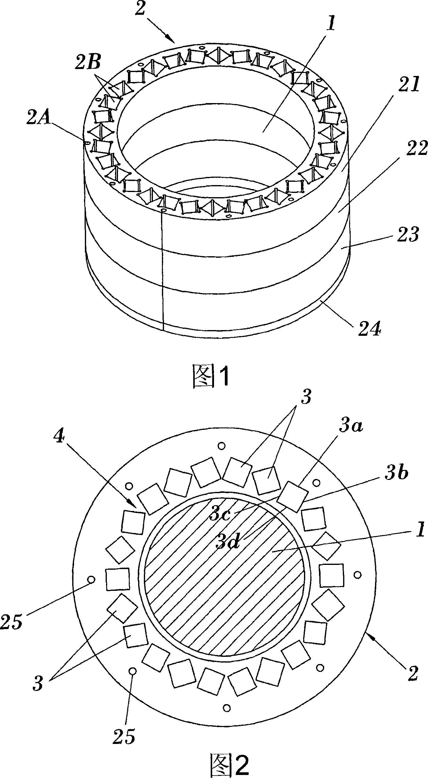
[0068] Figure 1 illustrates a possible preferred embodiment of the invention, and more particularly, a support structure 2 placed on top of a support or base 24, the support structure 2 comprising a plurality of support rings, for example aluminum rings, indicated as Ring 21, 22, 23. The free space 1 inside the ring is used to place samples or objects to be processed by magnetic particle separation.

[0069] As shown in ring 21 (which has the same or substantially the same construction as the other rings 22 and 23), the support ring has a series of holes or channels 2B in which magnets are disposed, so that despite attractive or repulsive forces between the magnets, The magnet remains stationary. The illustrated structure may also have a cover (not shown) for preventing vertical movement (ie movement parallel to the longitudinal axis of the support structure) of the magnets. In FIG. 1 , the hole 2A can also be seen, in which a rod, which can be made of brass or stainless ste...


PUM


Abstract

The invention relates to a method and device for separating magnetic particles, for separating magnetic particles from a sample housed in an inner space (1) of the separating device. In accordance with the invention, the magnetic field is generated with a specific configuration of the magnets (3). This specific configuration enables devices of different sizes with a reduced number of magnets or types of magnets to be established.

Description

technical field [0001] The invention relates to the technical field of magnetic particle separation. Background technique [0002] The separation of different types of particles has many applications. For example, in the fields of pharmacy, biology and pharmacology, it is often necessary to separate out defined components, such as samples, suspensions or solutions, such as defined types of antibodies, in order to analyze problems related to these components (eg, to diagnose diseases). Traditional methods used to achieve this type of separation of components, particles or molecules are separation methods by affinity columns and centrifugation. [0003] Another method that has been widely used in recent years is based on the separation method using magnetic particles. This method can be quickly and easily used for precise and reliable separation of components, for example, specific proteins, genetic material and biomolecules (see, e.g., Z M Saiyed, et al., "Application of Ma...

Claims


Application Information

Patent Timeline
Patent Type & Authority Applications(China)
IPC IPC(8): B03C1/035B03C1/28
CPCB03C1/035B03C1/0332B03C1/288B03C2201/22
Inventor 尤伊斯・米盖尔・马汀尼兹・嘎西亚古斯塔・蒙泰罗・卡斯提亚纳塞尔吉奥・嘎西亚・索特罗
Owner SEPMAG SYST
Why Eureka
Try Eureka