Medial mixer used for heat conducting oil boiler

A heat-conducting oil boiler and mixer technology, applied in the field of boilers, can solve the problems of inconsistent liquid medium temperature, limited length of collecting pipe, deviation of multi-channel small flow medium temperature, etc.

Inactive Publication Date: 2008-07-02
顾利平
View PDF0 Cites 2 Cited by
  • Summary
  • Abstract
  • Description
  • Claims
  • Application Information

AI Technical Summary

Problems solved by technology

Due to the large distribution of convection tube bundles and a wide range of distribution, the temperature of the multi-channel small flow media flowing out of the convection tube bundles has deviations, so the temperature of the liquid medium flowing into the collection pipe is inconsistent. Due to the limitation of the internal space of the boiler, the length of the collection pipe is limited. The multi-channel small flow medium cannot be mixed evenly in the collecting pipe before entering the coil or directly discharging, so the temperature consistency of the medium entering the coil or directly exiting is poor

Method used


Image

  • Medial mixer used for heat conducting oil boiler

Examples


Embodiment Construction

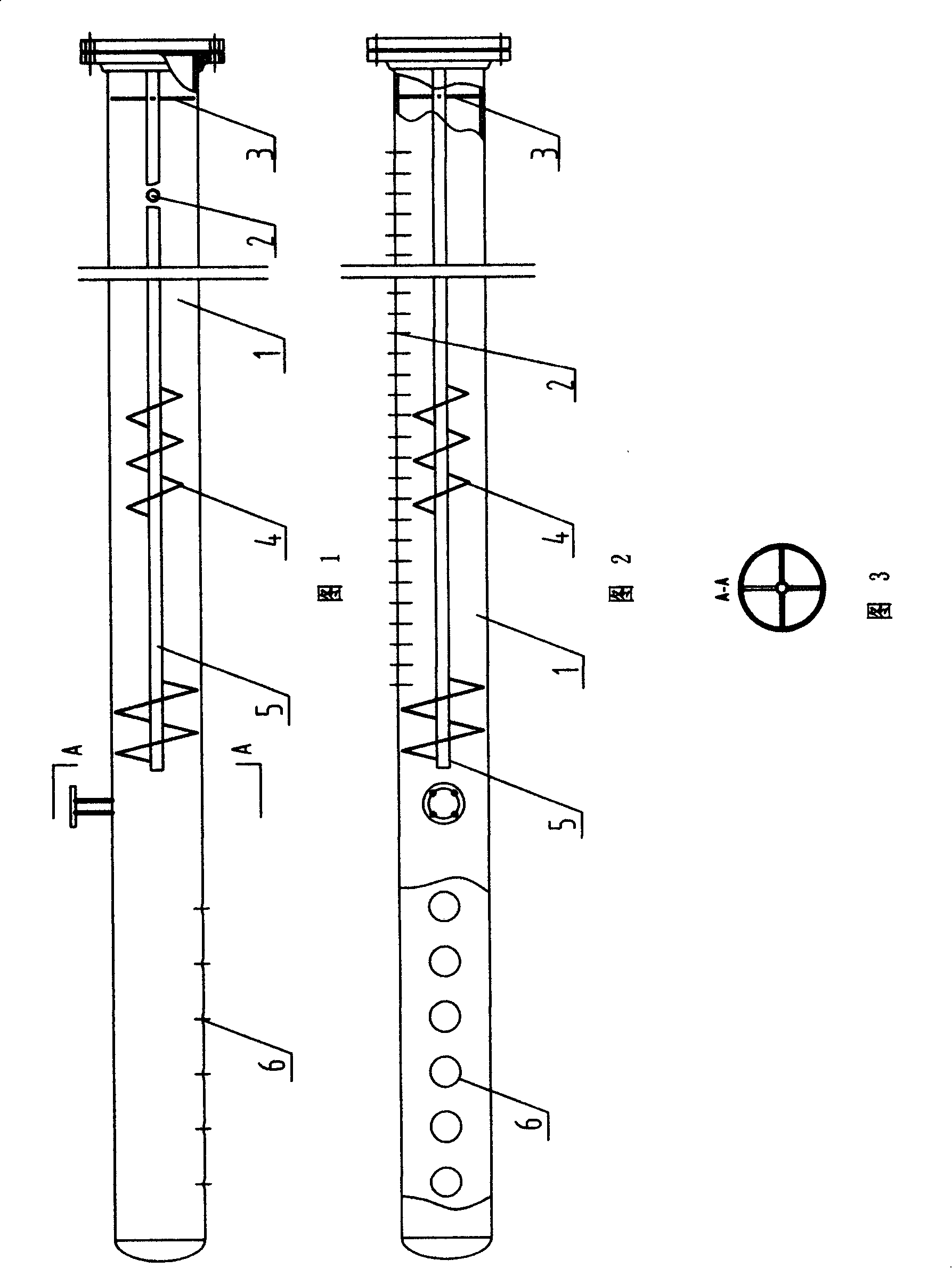
[0009] See Fig. 1, Fig. 2, the present invention comprises collection pipe 1, and the helical guide piece 4 is arranged in the collection pipe 1, and the helical guide piece 4 is sleeved on the support rod 5, and the two ends of the support rod 5 are installed on the cross support frame 3 (see figure 1, Fig. 3), the outer edge of support frame 3 is connected with the pipe wall of collecting pipe 1, and 2,6 are respectively the water inlet and the water outlet of collecting pipe.


PUM


Abstract

The invention relates to an intermediate mixer used in a heat-conduction oil boiler. The intermediate mixer can completely mix media that flow therein from multi-path convection bank bundles, and can keep good consistency in temperature. The intermediate mixer comprises a gallery and is characterized in that a spiral conductive sheet is arranged inside the gallery and is sleeved on a supporting rod, crisscross supporting frames are arranged at two ends of the supporting rod, and the outer margins of the crisscross supporting frames are connected with the wall of the gallery.

Description

(1) Technical field [0001] The invention relates to the technical field of boilers, in particular to an intermediate mixer used in a heat-conducting oil boiler. (2) Background technology [0002] In a traditional heat-conducting oil boiler, the liquid medium flowing out of the convection tube bundle directly flows into the collecting pipe and then enters the coil or goes out directly. Due to the large distribution of convection tube bundles and a wide range of distribution, the temperature of the multi-channel small flow media flowing out of the convection tube bundles has deviations, so the temperature of the liquid medium flowing into the collection pipe is inconsistent. Due to the limitation of the internal space of the boiler, the length of the collection pipe is limited. The multi-channel small-flow media cannot be mixed evenly in the converging pipe before entering the coil or directly discharging, so the temperature consistency of the medium entering the coil or direc...

Claims


Application Information

Patent Timeline
Patent Type & Authority Applications(China)
IPC IPC(8): F24H9/16F24H1/40
Inventor 顾利平
Owner 顾利平
Why Eureka
Try Eureka