

High order transmission channel correcting system
A transmission channel, advanced technology, applied in the field of correction system, can solve the problem of high calculation cost
- Summary
- Abstract
- Description
- Claims
- Application Information
AI Technical Summary
Problems solved by technology
Method used
Image

Examples
Embodiment Construction
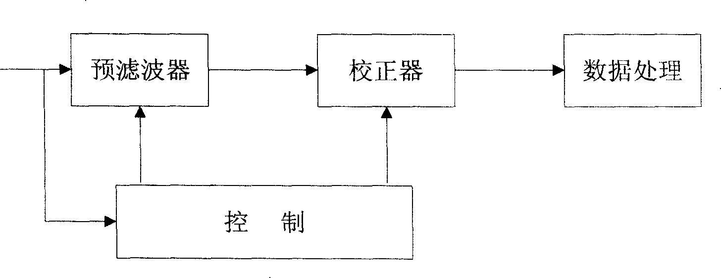
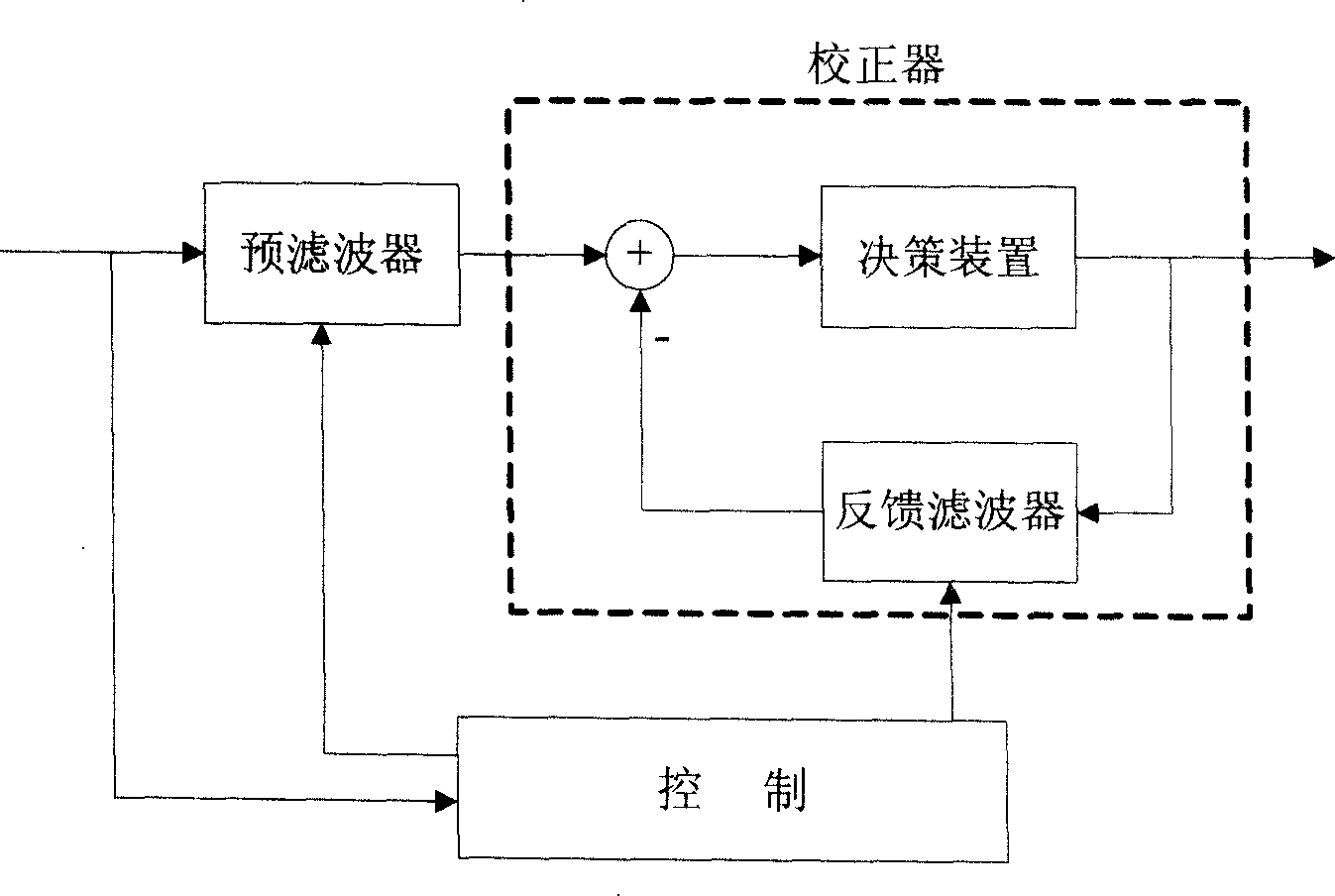
[0039] A system for calibrating high-order transmission channels, including a data memory, a corrector rotation unit, a pre-filter rotation unit, and a count judgment unit, wherein:
[0040] A data memory for storing channel parameters;
[0041] A calibrator rotation unit, configured to perform a rotation operation to obtain an adjustment coefficient of the calibrator;
[0042] A pre-filter rotation unit, configured to perform a rotation operation to obtain an adjustment coefficient of the pre-filter;
[0043] The counting judging unit is used for counting and judging the times of rotation and row shifting.
[0044] Combine below Figure 4 The functions and operations of each unit of the system in the embodiment are described in detail.
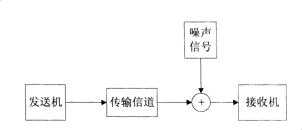
[0045] Step 110, the receiver R receives the received data Xk in the received data packet;
[0046] The received data X k The data packet blocks are transmitted on the time slots of the time division multiple access transmission system. ...
PUM
 Abstract
Description
Claims
Application Information