Imaging apparatus
An imaging device, image sensor technology, used in image communication, television, optics, etc.
- Summary
- Abstract
- Description
- Claims
- Application Information
AI Technical Summary
Problems solved by technology
Method used
Image

Examples
no. 1 example
[0032]
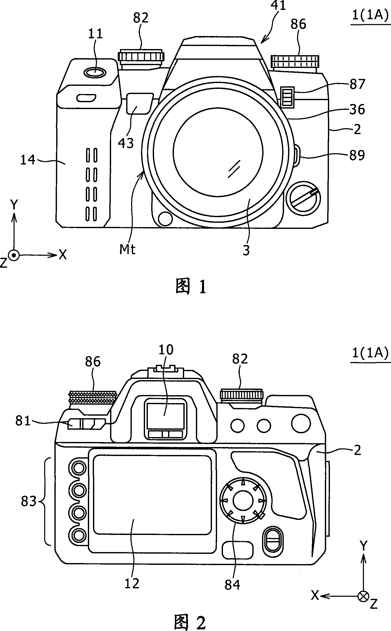
[0033] 1 and 2 are views showing the external structure of the imaging apparatus 1 (1A) according to the first embodiment of the present invention. Specifically, FIG. 1 is a front view showing the external front structure of the imaging device 1, and FIG. 2 is a rear view showing the external back structure of the imaging device 1. The illustrated imaging device 1 is provided in the form of a single-lens reflex digital camera with interchangeable lenses.
[0034] As shown in FIG. 1, the imaging apparatus 1 has a camera body unit (camera body) 2. The interchangeable electronic imaging lens unit (interchangeable lens) 3 is detachably mounted on the camera body unit 2.
[0035] The imaging lens unit 3 is mainly configured with components such as a lens barrel 36 and a lens group 37 (see FIG. 3) housed in the lens barrel 36 together with an aperture. The lens group 37 (image acquisition optical system) includes a lens such as a focus lens adapted to move in the optical axis ...
no. 2 example
[0120] The second embodiment relates to an improvement over the first embodiment. The following description focuses on the differences from the first embodiment. FIG. 14 is an enlarged cross-sectional view showing the internal structure around the pentagonal mirror 65 of the imaging apparatus 1B according to the second embodiment.
[0121] As shown in FIG. 14, the imaging device 1B is different from the imaging device 1A in that the former uses a half mirror 73 instead of the beam splitter 71.
[0122] The half mirror 73 also provides the same function as the beam splitter 71. For example, it includes a function of changing the traveling direction of light traveling along the optical path PB during framing using EVF, and a function of an optical lens that allows traveling along the optical path PE during framing using OVF.
[0123] This type of structure can also obtain the same effect as the first embodiment.
no. 3 example
[0125] The third embodiment involves a different improvement to the first embodiment. The following description focuses on the differences from the first embodiment. 15 is an enlarged cross-sectional view showing the internal structure around the pentagonal mirror 65 of the imaging apparatus 1C according to the third embodiment.
[0126] As shown in FIG. 15, speaking of the main point, the structure adopted by the imaging device 1C appears to approximately reverse the positional relationship between the image sensor 7 and the photometric sensor 79 with respect to the imaging device 1A.
[0127] Specifically, the imaging lens 67 and the image sensor 7 are provided on the optical path PB, and more specifically, on the optical path (transmitted optical path) PB generated by the transmission through the beam splitter 71 3. The imaging lens 72 and the photometric sensor 79 are provided on the optical path PE, more specifically, on the optical path PE3 generated by the beam splitter 71 ...
PUM
 Abstract
Description
Claims
Application Information
 - Generate Ideas
- Intellectual Property
- Life Sciences
- Materials
- Tech Scout
- Unparalleled Data Quality
- Higher Quality Content
- 60% Fewer Hallucinations
Browse by: Latest US Patents, China's latest patents, Technical Efficacy Thesaurus, Application Domain, Technology Topic, Popular Technical Reports.
© 2025 PatSnap. All rights reserved.Legal|Privacy policy|Modern Slavery Act Transparency Statement|Sitemap|About US| Contact US: help@patsnap.com