Vacuum line and method for monitoring same

A technology of vacuum pipelines and measuring devices, which is applied in the direction of pump testing, measuring devices, and testing of machine/structural components, etc. It can solve problems such as pump unit testing that is difficult to interrupt the manufacturing process, and blockage prediction of exhaust systems that cannot be pumped.

Inactive Publication Date: 2008-07-02
ALCATEL LUCENT SAS
View PDF3 Cites 6 Cited by
  • Summary
  • Abstract
  • Description
  • Claims
  • Application Information

AI Technical Summary

Problems solved by technology

[0012]This method cannot be carried out during the continuous manufacturing phase, because it is difficult to interrupt the manufacturing process to test the pump unit due to organizational reasons
In addition, the method cannot predict clogging of the exhaust system of the pump

Method used


Image

  • Vacuum line and method for monitoring same
  • Vacuum line and method for monitoring same
  • Vacuum line and method for monitoring same

Examples


Embodiment Construction

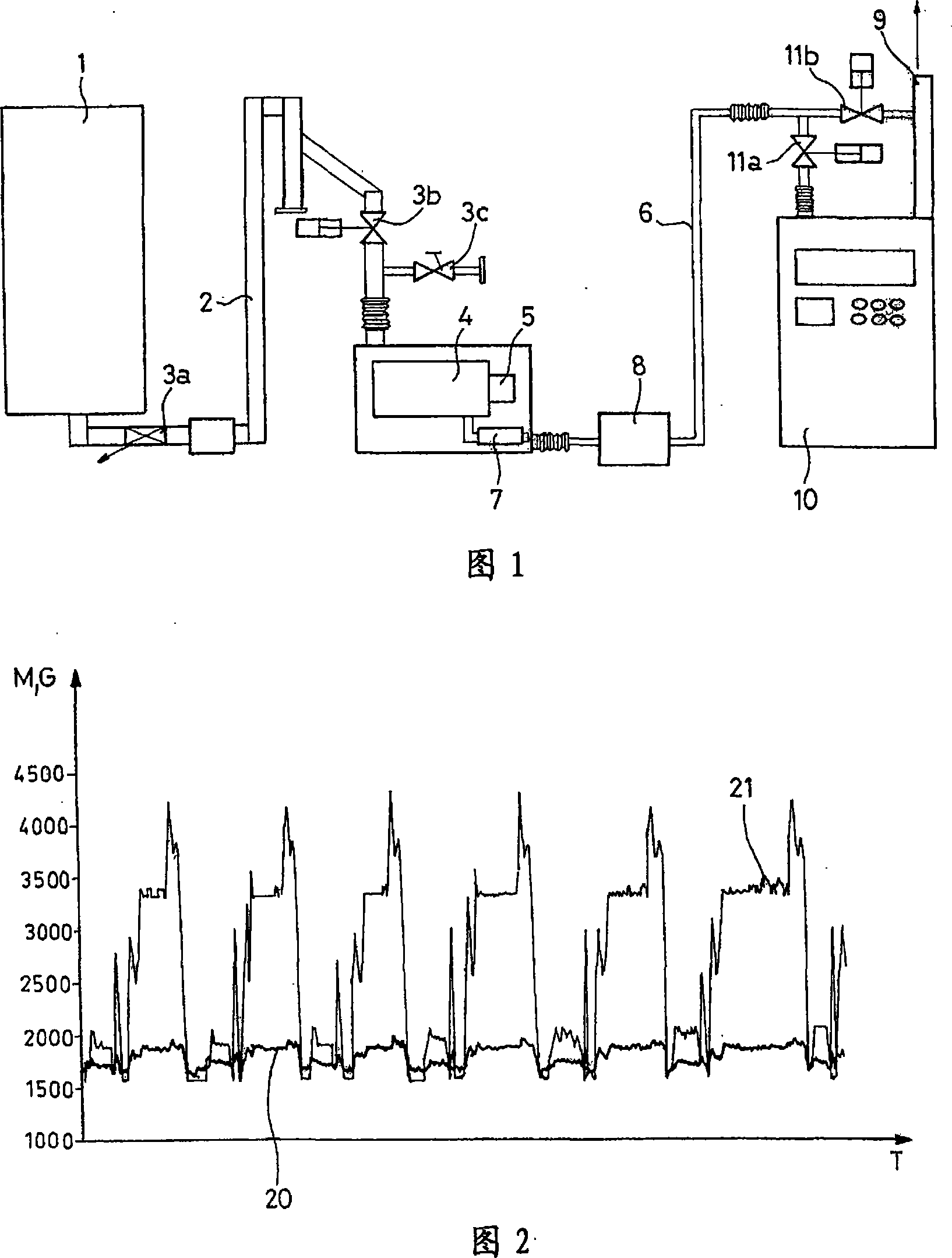
[0056] The facility shown in Figure 1 comprises a processing chamber 1 for processing substrates. For example, the process chamber can be used to perform deposition, etch, or ion implantation processes, or to perform thermal treatments, as used in the fabrication of microelectronic devices on silicon wafers. The treatment may also be micromachining of the semiconductor substrate in the manufacture of micro-electro-mechanical systems (MEMS) or micro-opto-electromechanical systems (MOEMS). The processing chamber 1 is connected to a pump body 4 driven by a motor 5 through a pipe 2 equipped with valves 3a, 3b and 3c. The pump body 4 is connected with the exhaust pipe 6 through a muffler 7 . A collector 8 may be installed on the exhaust pipe 6 to collect the solid by-products produced in the reaction. When gaseous by-products of the processes performed are not suitable to be discharged from the general exhaust port 9, the gases are vented through the treatment facility 10 using v...


PUM


Abstract

The present invention provides a vacuum line for pumping gas from a process chamber, the vacuum line comprising at least: a pump unit comprising a pump body and a motor; a gas exhaust system; first measurement means for measuring a functional parameter relating to the motor; second measurement means for measuring a functional parameter relating to the exhaust system; and prediction means for calculating the duration of use of the vacuum line. The prediction means calculate the duration of utilization of the vacuum line prior to failure of the pump unit from the measurement of a functional parameter relating to the motor provided by the first means and the measurement of a functional parameter relating to the exhaust system provided by the second means. In a variant, the vacuum line further includes third measurement means for measuring a functional parameter relating to the pump body, and the prediction means calculate the duration of use while taking account of the measurement of this parameter.

Description

technical field [0001] The present invention relates to predictive and preventive maintenance of vacuum lines associated with process chambers. More specifically, the present invention relates to tracking the progress of phenomena that contaminate vacuum lines with solids (blockage, seizure, etc.). The invention also extends to a method for monitoring said phenomena in order to make a diagnosis and enable preventive maintenance measures to be instituted. Background technique [0002] Vacuum lines containing at least one pump unit are used in many processes that use gases and require sub-atmospheric pressures. Unfortunately, the gases used in these processes can be converted to solid by-products. These by-products can be deposited in the form of film on the inner surface of the vacuum pipe, especially on the surface of pipes, valves, and other accessories, and can also be deposited on the moving parts and stationary parts of the pump, or these by-products Will collect in t...

Claims


Application Information

Patent Timeline
IPC IPC(8): F04B37/14F04B37/08F04B51/00G01M99/00
CPCF04C23/00F04B37/14F04B51/00F04C2270/03F04C2270/80F04B37/08H01L21/02
Inventor N·贝古
Owner ALCATEL LUCENT SAS
Why Eureka
Try Eureka