Multiple-row angular contact antifriction bearing, particularly for mounting the bevel pinion shaft in a motor vehicle rear axle differential

A technology for rolling bearings and automobile rear axles, which is applied to rolling contact bearings, roller bearings, shafts and bearings, etc., and can solve problems such as increasing axial installation space, increasing manufacturing costs, and raceway wear

Inactive Publication Date: 2008-07-02
SCHAEFFLER TECH AG & CO KG
View PDF1 Cites 6 Cited by
  • Summary
  • Abstract
  • Description
  • Claims
  • Application Information

AI Technical Summary

Problems solved by technology

[0004]However, this application of the replacement of tapered roller bearings by tandem-angular contact rolling bearings proved to be disadvantageous in practice, due to the successive arrangement of the angular contact rolling bearings for the balls The raceway and due to the larger ball diameter to achieve the required load carrying capacity and due to its bearing cage requires an increased axial installation space compared to tapered roller bearings
If such angular contact rolling bearings are also to have a greater load-carrying capacity than tapered roller bearings, then the bearing seats need to be cumbersomely modified in the housing of the rear axle differential, which disadvantageously increases their production costs
In addition, such two-row angular contact rolling bearings also have increased technical and material costs in bearing production compared to tapered roller bearings, so that their production costs are likewise increased.
In addition, in such angular contact rolling bearings, the configuration in which the raceway radii are necessarily different compared to the ball radii has proven to be disadvantageous, whereby the balls are only in point contact with their raceways and thus cause friction against the raceways in the area of ​​the pressure angle axis. Increased surface pressure of the raceway, which leads to increased raceway wear
In addition, due to the balls which normally overlap the shoulder edge of the raceway, but which bear against the shoulder edge after the close contact has been eliminated, high edge stresses occur in the area of ​​this shoulder edge, thereby causing wear of the ball raceway. further increases and thus significantly reduces the service life of such angular contact rolling bearings

Method used


Image

  • Multiple-row angular contact antifriction bearing, particularly for mounting the bevel pinion shaft in a motor vehicle rear axle differential
  • Multiple-row angular contact antifriction bearing, particularly for mounting the bevel pinion shaft in a motor vehicle rear axle differential
  • Multiple-row angular contact antifriction bearing, particularly for mounting the bevel pinion shaft in a motor vehicle rear axle differential

Examples


Embodiment Construction

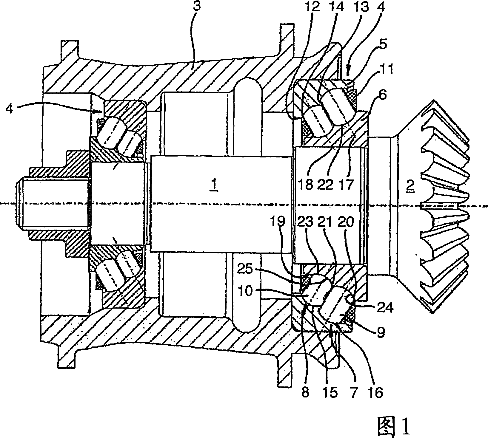
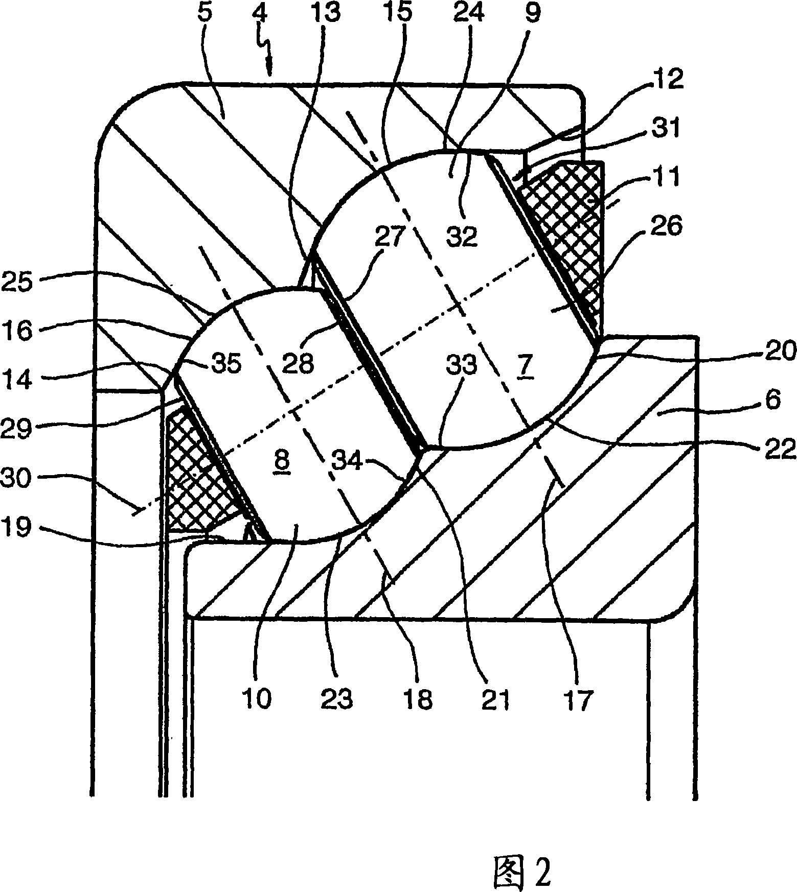
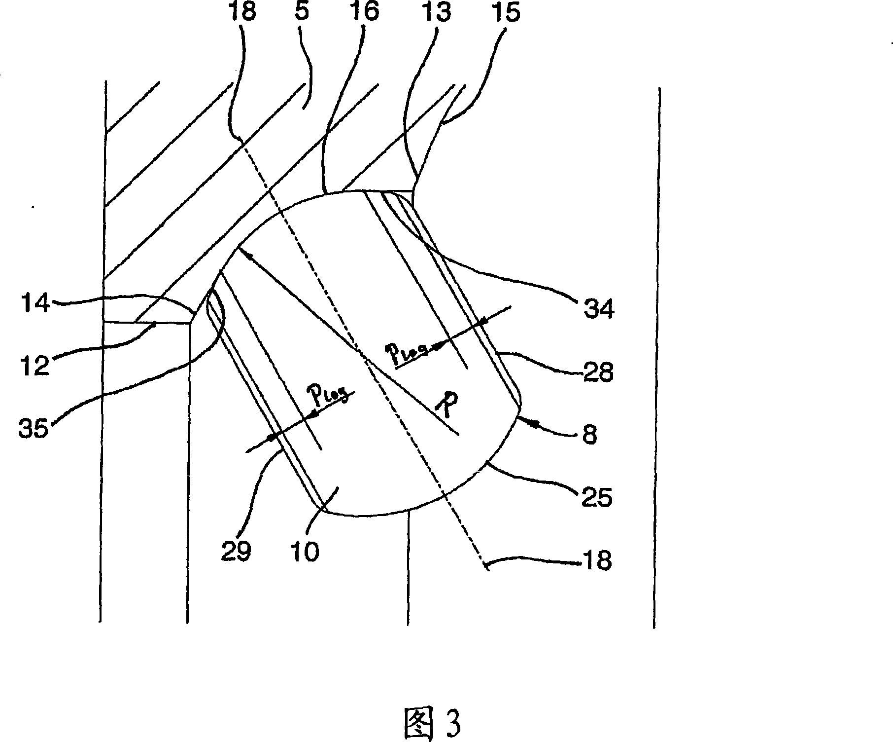
[0019] A part of the rear axle differential of the vehicle can be seen clearly from FIG. 1 , with which the engine torque can be transmitted to the on the drive shaft of the car. The bevel gear shaft 1 is fixed here in the housing 3 of the rear axle differential via two spaced-apart angular contact roller bearings 4 arranged opposite each other, which each substantially comprise an outer bearing ring 5 and An inner bearing ring 6 and a plurality of rolling elements 9 , 10 arranged next to each other in two rows 7 , 8 between the respective bearing rings 5 ​​, 6 , which are held at uniform distances in the circumferential direction by a bearing cage 11 . In this case, the inner sides 12 of the outer bearing rings 5 ​​of the two angular contact rolling bearings 4 are formed with two adjacent raceways 15 , 16 delimited on one side by a shoulder 13 , 14 , which are in contact with the inner bearings. On the outer side 19 of the ring 5 two adjacent raceways 22 , 23 which are like...


PUM


Abstract

The multiple-row angular contact antifriction bearing has an outer bearing ring, an inner bearing ring, and roll bodies, which are arranged at least in two rows next to one another between the bearing rings. The roll bodies are ball discs having two lateral surfaces that are symmetrically flattened from a spherical basic shape whose raceways are arranged inside the bearing rings, abutting against one another so that the respectively adjacent roll bodies of each row have their lateral surface pointing toward one another and arranged directly next to one another on a transversal axis situated at a right angle to the pressure angle axes. These lateral surfaces also provide mutual guide surfaces.

Description

technical field [0001] The invention relates to a multi-row angular contact rolling bearing according to the features of the preamble of claim 1, and it is used particularly advantageously for mounting bevel gear shafts in rear axle differentials of motor vehicles. Background technique [0002] It is generally known to those skilled in the field of vehicle transmission technology that in a vehicle with rear axle drive the engine torque is transmitted downstream of the automatic transmission or transmission via a bevel gear shaft with bevel gears and via a driven bevel gear to the two halves The drive shaft consists of a shaft, wherein the speed difference between the two drive shafts is eliminated when cornering through a differential gear consisting of several differential gears. The bevel gear shaft is fixed in the housing of the rear axle differential via two angular contact roller bearings spaced apart from one another, which are highly stressed due to the high torque to...

Claims


Application Information

Patent Timeline
Patent Type & Authority Applications(China)
IPC IPC(8): F16C19/38F16C19/50F16C19/56F16C33/26F16H57/02F16H48/42
CPCF16H2048/423F16C2240/80F16C19/56F16C33/36F16C19/38F16C19/505F16C2361/61F16C19/548
Inventor H·霍夫曼H·德普林R·普兰克A·格鲁瑙
Owner SCHAEFFLER TECH AG & CO KG
Why Eureka
Try Eureka