Pump unit for nuclear installations

A technology for pumping devices and nuclear facilities, which is applied to the components of pumping devices, pumping devices, pumps, etc. for elastic fluids, can solve problems such as inability to eliminate, and achieve the effect of avoiding material contact and minimizing half-frequency whirl.

Inactive Publication Date: 2012-05-23
FRAMATOME ANP
View PDF1 Cites 0 Cited by
  • Summary
  • Abstract
  • Description
  • Claims
  • Application Information

AI Technical Summary

Problems solved by technology

However, the stated problem cannot be eliminated by this measure

Method used


Image

  • Pump unit for nuclear installations
  • Pump unit for nuclear installations

Examples


Embodiment Construction

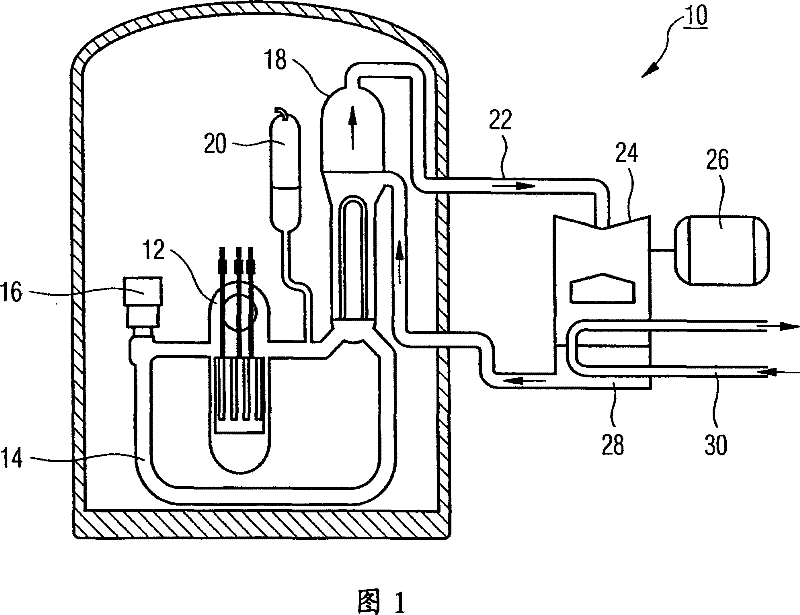
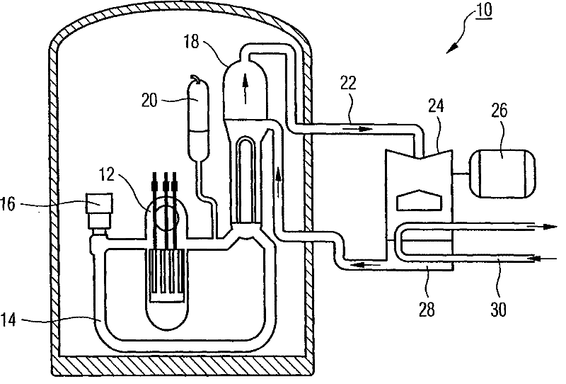
[0013] In the pressurized water reactor 10, generally "light" water is used as both moderator and coolant. Therefore, the pressurized water reactor is of the type of light water reactor.

[0014] The pressurized water reactor 10 has two main cooling circuits, a primary cooling circuit and a secondary cooling circuit. The primary cooling circuit 14 is composed of a reactor pressure vessel 12 including a reactor core, a main coolant pump 16 , a steam generator 18 , and piping for connection. Furthermore, a pressure vessel 20 is provided in a known manner.

[0015] The main coolant pump 16 delivers the coolant (purified water, approximately 290° C.) into the thick-walled reactor pressure vessel 12 made of steel, where it flows initially downwards in an annular channel. The coolant is diverted at the bottom of the vessel and then flows from the bottom up around the fuel rods in the reactor pressure vessel 12 . Here, the coolant cools the fuel rods, whereby the coolant is heated...


PUM


Abstract

The invention relates to a pump device (16) for a nuclear equipment (10) (such as water pressing reaction pile). The pump device is provided with a vertical axle (standing axle) which is guided through a sliding bearing. In the pump device, at least one sliding bearing is designed to helix groove bearing to avoid the axle vibration caused by the bearing and improve the service life of the pump device. For instance, the pump device (16) is preferably used as the cooling agent pump of the water pressing reaction pile and the cycle of the boiling water reaction pile.

Description

technical field [0001] The invention relates to a pump arrangement for nuclear installations, in particular to such a pump arrangement with a vertically oriented shaft (vertical shaft). Background technique [0002] Different pump arrangements are required in nuclear installations, for example coolant pumps for pressurized water reactors or circulation pumps for boiling water reactors. Such pump devices are generally designed with large dimensions, have a vertically oriented shaft and must meet the highest quality requirements with regard to output power and durability, especially for reasons of technical safety. [0003] In machines with a vertically oriented shaft (the shaft is guided by plain bearings and on which, as is usually the case in axial and semi-axial pumps, there is low radial hydraulic force), the known It is the vibration of half-frequency whirl (Halbfrequenzwirbel) (also often called ω / 2 whirl). Such periodic excitations lead to rough running, which can al...

Claims


Application Information

Patent Timeline
Patent Type & Authority Patents(China)
IPC IPC(8): G21D1/04F04D29/04F16C33/10F16C17/14
CPCF04D29/0413G21D1/04Y02E30/40Y02E30/00Y02E30/30
Inventor 京特·舒尔茨海因茨·克特尔马克斯·黑勒
Owner FRAMATOME ANP
Why Eureka
Try Eureka