
Detection method, detection device and logic chip

The technology of a detection method and a detection device is applied in the direction of preventing/detecting errors through diversity reception, space transmission diversity, transmission system, etc., and can solve the problems of heavy detection method workload, multi-sector connection errors, antenna connection errors, etc., Achieve the effects of avoiding positioning difficulties, saving hardware costs, and saving costs

Inactive Publication Date: 2008-07-09
HUAWEI TECH CO LTD
View PDF0 Cites 32 Cited by
  • Summary
  • Abstract
  • Description
  • Claims
  • Application Information

AI Technical Summary

Problems solved by technology

[0008] The first aspect of the present invention is to provide a detection method to solve the problems in the prior art that multi-sectors are prone to connection errors and the existing detection method has a large workload, is complicated, and is difficult to construct after positioning. Realize that the antenna connection error can be detected with a simple method before or after the operation of the base station, and the possible connection error can be eliminated before operation, so as to avoid problems and positioning difficulties after the operation of the base station
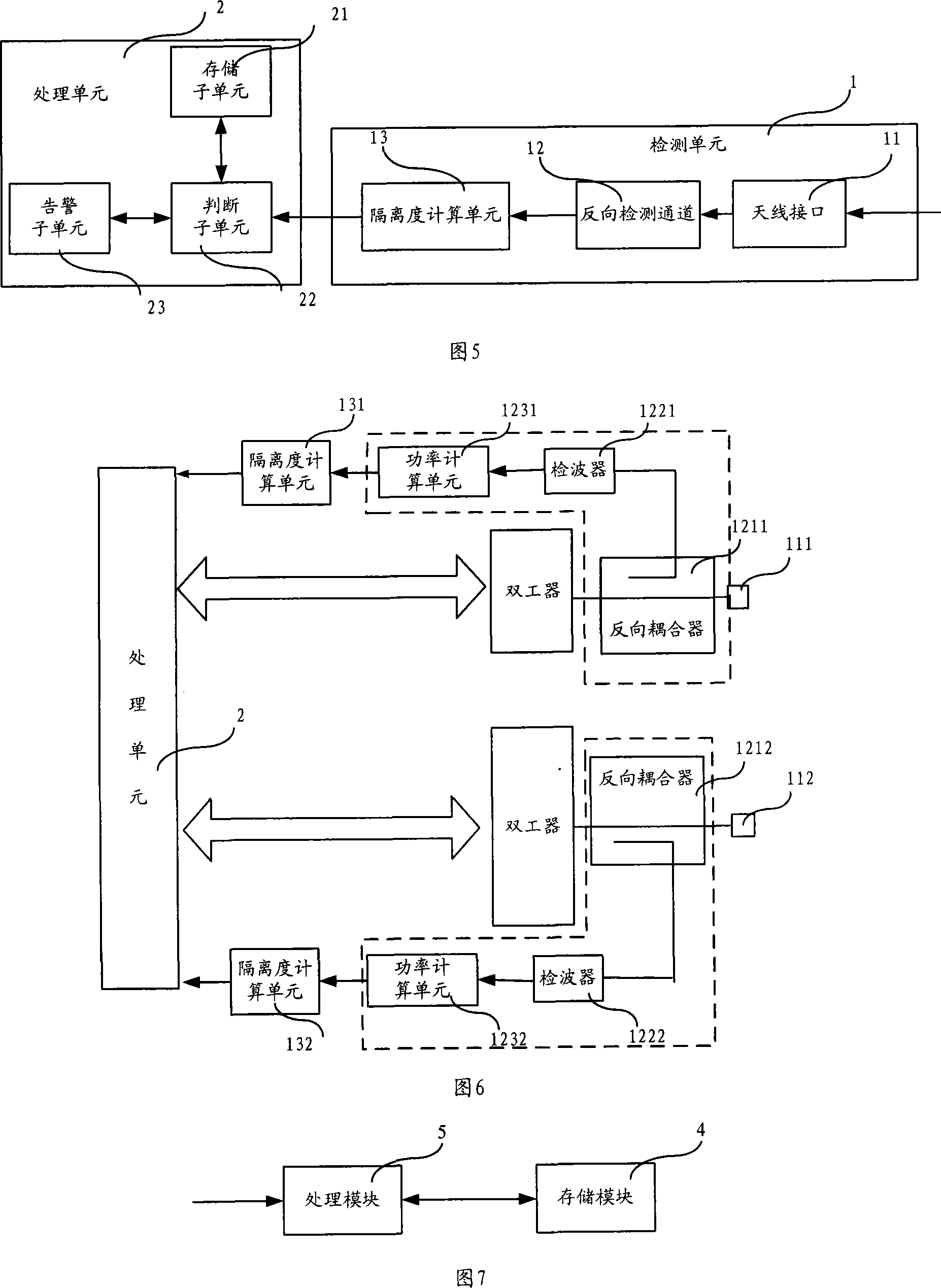
[0009] The second aspect of the present invention is to provide a detection device to solve the problem of multi-sector connection errors in the prior art, realize the use of existing equipment, save hardware costs, and detect the antenna before the operation of the base station Whether it is wrong, to avoid problems and positioning difficulties after the operation of the base station
[0010] The third aspect of the present invention is to provide a logic chip to solve the problem that multi-sectors are prone to connection errors in the prior art, and to realize the detection of antenna connection errors with a simple method

Method used


Image

  • Detection method, detection device and logic chip
  • Detection method, detection device and logic chip
  • Detection method, detection device and logic chip

Examples


Embodiment Construction

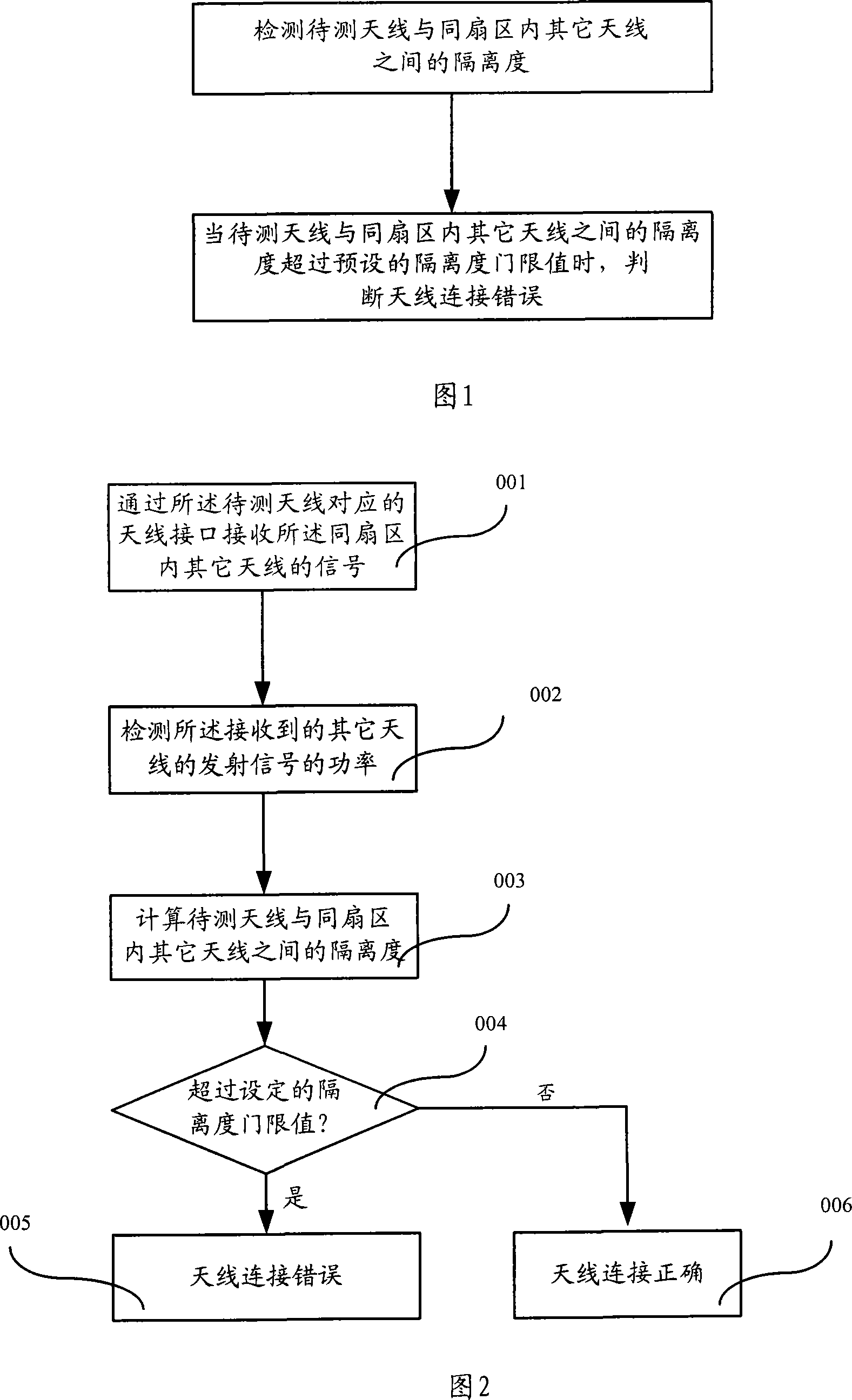
[0029] Referring to FIG. 1 , it is a flow chart of Embodiment 1 of the detection method of the present invention. As shown in Figure 1, this embodiment includes:

[0030] Detect the isolation between the antenna under test and other antennas in the same sector;

[0031] When the isolation between the antenna to be tested and other antennas in the same sector exceeds the preset isolation threshold, it is determined that the antenna is connected incorrectly.

[0032] This embodiment detects the isolation between the antenna to be tested and other antennas in the same sector to determine whether there is an antenna connection error. Since the isolation between antennas in different sectors is much greater than the isolation between antennas in the same sector, therefore An isolation threshold can be set. When it is detected that the isolation between antennas in the same sector exceeds the set threshold, it can be known that there is an antenna connection error (it may be that a...


PUM


Abstract

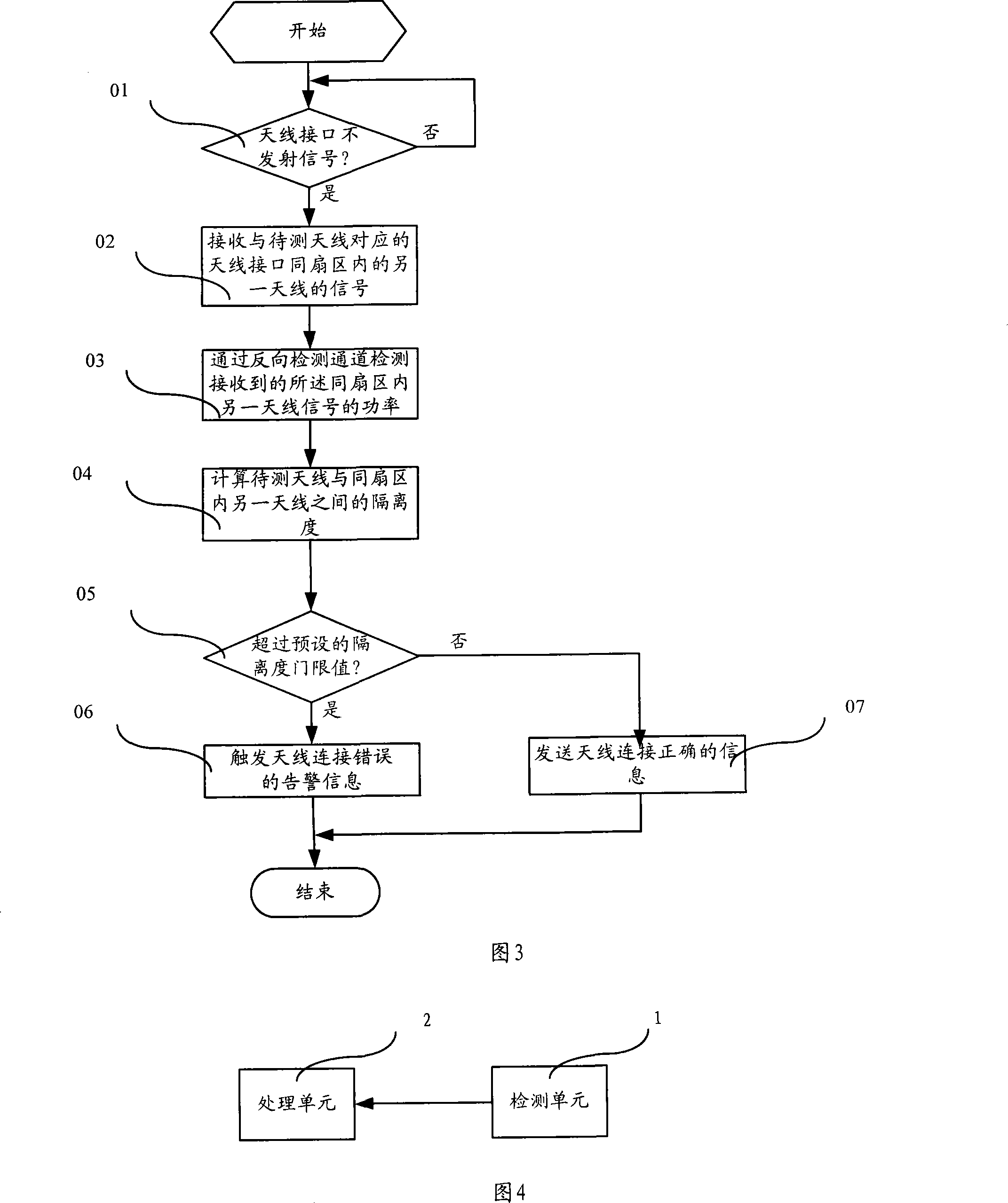
The invention relates to a detection method, a detection device and a logic chip, wherein, the embodiment of the method comprises the following steps of detecting the isolation degree between an antenna to be detected and other antennas in the same sector, and determining that the antenna has connection errors if the isolation degree between the antenna to be detected and other antennas in the same sector exceeds a predefined threshold of isolation degree. Each embodiment of the invention uses a reverse power detection channel owned by existing equipments, thus saving hardware cost, and the embodiment detects the signal of other antennas in the same sector which is received by the reverse power detection channel, so as to directly determine whether the antenna has connection errors, thus effectively solving the problems that connection errors are easy to appear due to a plurality of sectors in existing techniques and the existing detection methods have large and complex workload and large construction difficulty after location, etc.

Description

technical field [0001] The invention relates to a detection method, a detection device and a logic chip, in particular to a method, a device and a logic chip for detecting the connection status of an antenna in a sector, belonging to the technical field of wireless communication. Background technique [0002] In the prior art, most of the outdoor coverage of the communication system adopts a multi-sector approach to solve the problem of wide coverage for large-capacity users. The application of multi-sector needs to set multiple antennas correspondingly. Therefore, it is easy to have an incorrect connection between the antenna and the sector interface of the corresponding base station, which will lead to interference problems between different sectors of adjacent cells or a decrease in diversity reception performance, which will further cause communication system failures. Performance drops. [0003] In the prior art, after the construction of the base station and the erect...

Claims


Application Information

Patent Timeline
IPC IPC(8): H04B7/04H04L1/06
CPCH04B17/0062H04B17/00H04B17/0022H04B17/21H04B17/17
Inventor 李玉林
Owner HUAWEI TECH CO LTD
Learn More