
A multi-input and multi-output recoding processing method of multi-subchannel

A sub-channel, multi-output technology, applied in the field of multi-sub-channel MIMO precoding processing, can solve the problems of reduced system performance, low possibility, interference, etc.

Inactive Publication Date: 2008-07-09
BEIJING UNIV OF POSTS & TELECOMM +1
View PDF0 Cites 49 Cited by
  • Summary
  • Abstract
  • Description
  • Claims
  • Application Information

AI Technical Summary

Problems solved by technology

Similarly, when multiple sub-channels are used, since the multiple precoded vectors selected in the codebook are less likely to completely match the actual channel, inter-sub-channel interference is generated between each sub-channel, thereby reducing the system performance

Method used


Image

  • A multi-input and multi-output recoding processing method of multi-subchannel
  • A multi-input and multi-output recoding processing method of multi-subchannel
  • A multi-input and multi-output recoding processing method of multi-subchannel

Examples


Embodiment 1

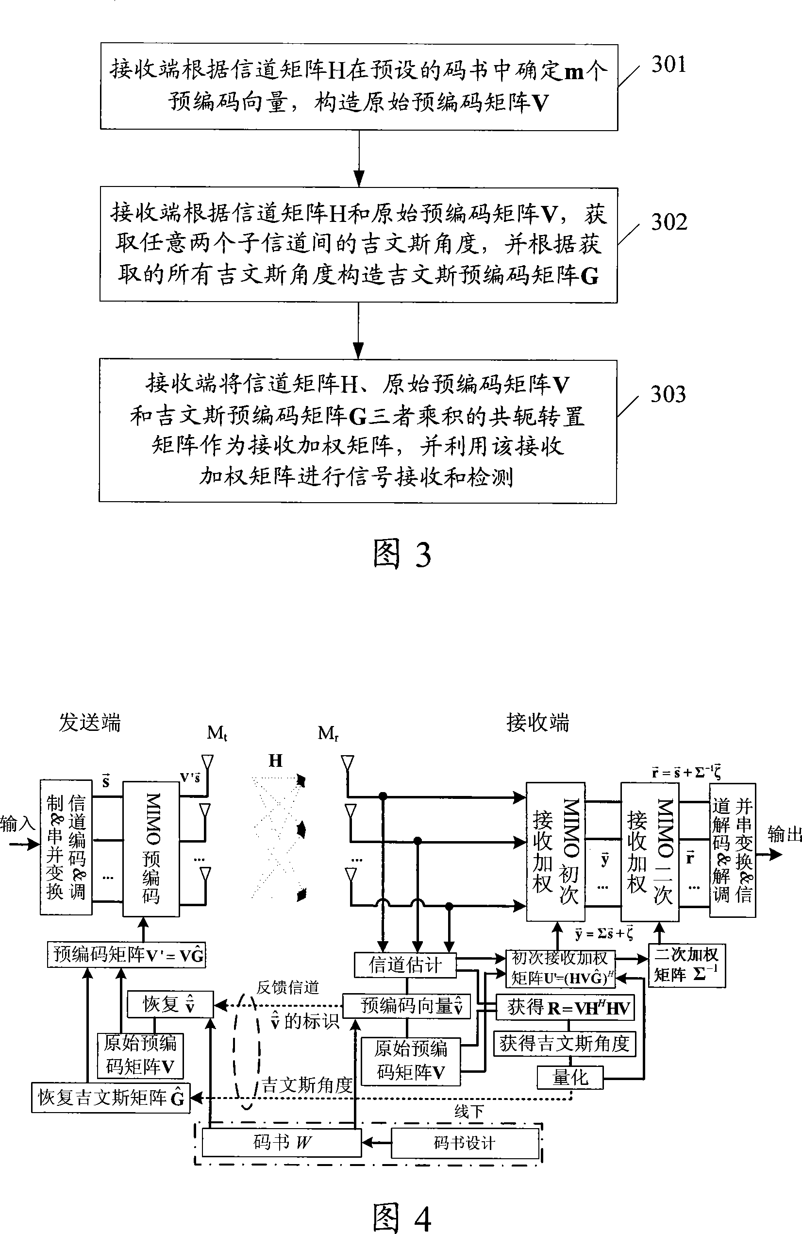
[0099] The method in this embodiment is implemented in the multi-subchannel MIMO system shown in FIG. 4 . As shown in Figure 4, the multi-subchannel precoded MIMO system has M t transmit antenna M r receiving antennas, the channel matrix is ​​H, the number of sub-channels used by the system is m, and m≤min(M t ,M r ). The sending end and the receiving end have the same codebook W, and W consists of N unitary vectors constitute. The system has a low-rate, no-delay, and no-error feedback channel for feeding back precoding information.

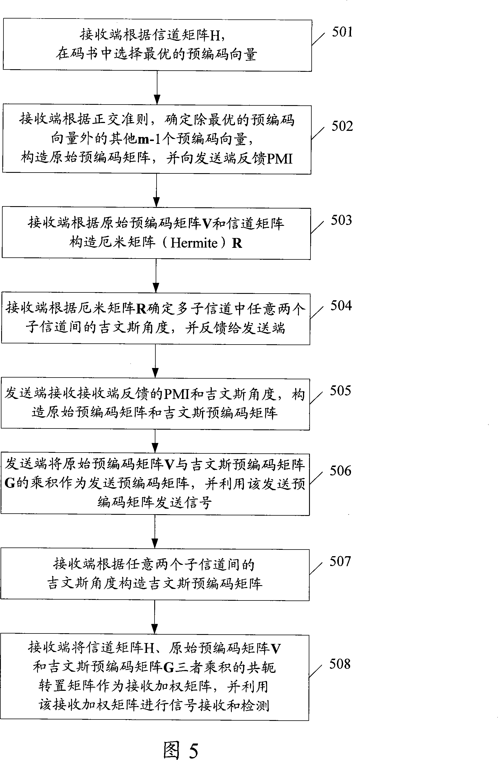
[0100] FIG. 5 is a specific flowchart of a precoding processing method based on the MIMO system shown in FIG. 4 . As shown in Figure 5, the method includes:

[0101] In step 501, the receiving end selects the optimal precoding vector in the codebook according to the channel matrix H.

[0102] In this step, the receiving end first performs channel estimation according to the received signal, and obtains the channel matrix H from the sendi...

Embodiment 2

[0158] FIG. 6 is a specific flow chart of the precoding processing method in Embodiment 2 of the present invention. This embodiment is implemented in a TDD system. As shown in Figure 6, the method includes:

[0159] Step 601, the sending end performs channel estimation according to the received signal, and uses the estimation result as the channel matrix H from the sending end to the receiving end.

[0160] In this step, using the reciprocity of the uplink and downlink channels in the TDD system, that is, the characteristics of the same characteristics of the uplink and downlink channels, the estimated channel matrix from the receiving end to the sending end is used as the channel matrix from the sending end to the receiving end. In this way, it can be directly The precoding vector and the Givens angle are calculated at the transmitting end without feedback from the receiving end.

[0161] In step 602, the transmitting end selects the optimal precoding vector in the codebook...


PUM


Abstract

The invention discloses a MIMO pre-coding method with a plurality of subchannels and a pre-coding signal receiving method; in a sender and a receiver, m pre-coding vectors which are the same with that of the receiver are determined in a predefined code book for constructing an original pre-coding matrix V, wherein, m is the number of the subchannels; the Givens angles between two subchannels in the subchannels are acquired, and a Givens pre-coding matrix G is constructed according to all the required Givens angles. The sender uses the product of the original pre-coding matrix V and the Givenspre-coding matrix G as a sending pre-coding matrix and sends signals by using the sending pre-coding matrix; the receiver uses a conjugate transpose matrix of the product of a signal channel matrix H, the original pre-coding matrix V and the Givens pre-coding matrix G as a receiving weight matrix and implements signal receiving and detecting by using the receiving weight matrix. The method of theinvention can greatly reduce the interference among subchannels and improve system performance.

Description

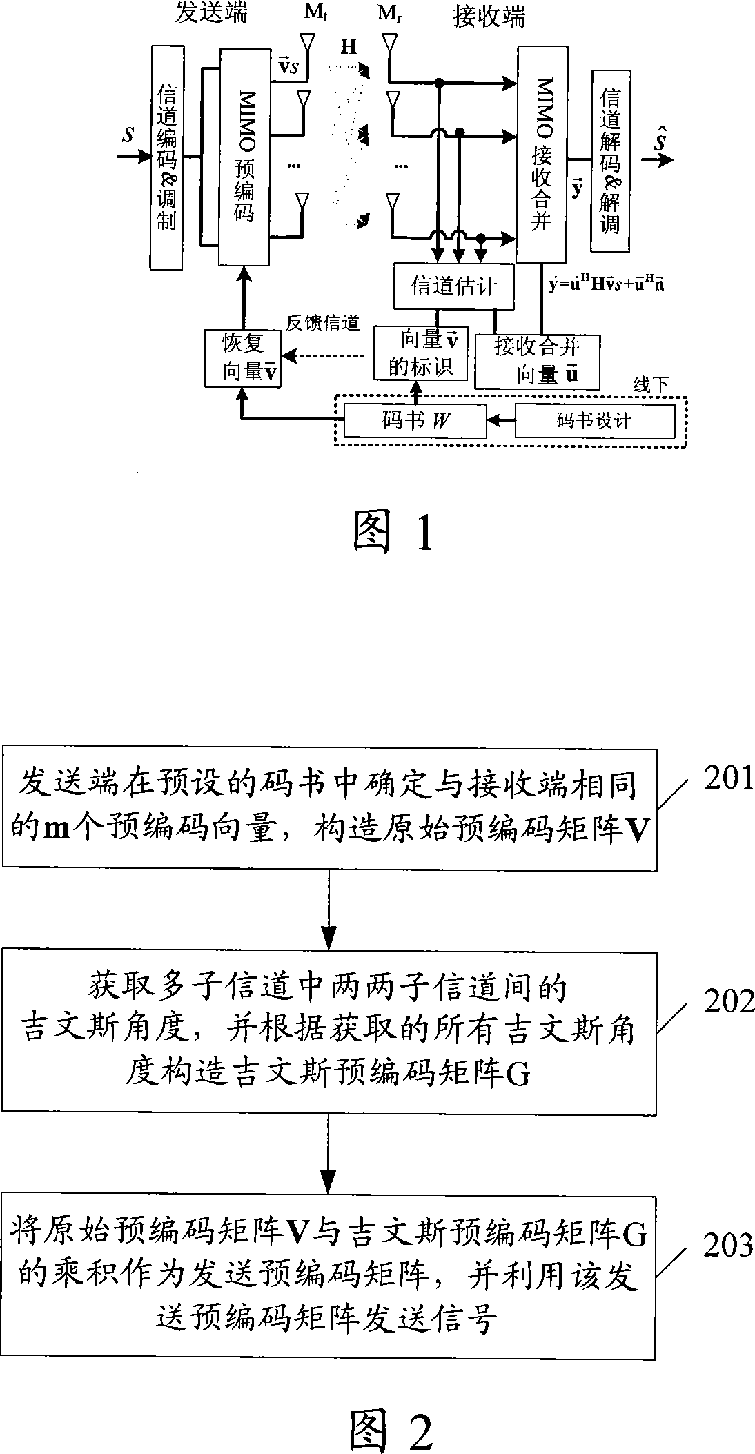
technical field [0001] The present invention relates to multiple-input multiple-output (MIMO) technology, in particular to a multi-subchannel MIMO precoding processing method. Background technique [0002] Multi-antenna technology can provide higher frequency band utilization, and is a hot research topic in the current wireless communication field. At present, the most important multi-antenna technologies are based on space division multiplexing (SDM) schemes, such as: D-BLAST, V-BLAST; schemes based on transmit diversity, such as: STTC, STBC; MIMO schemes based on transmitter precoding Wait. [0003] FIG. 1 is a schematic diagram of an existing codebook-based precoding MIMO scheme. For simplicity, only the precoding MIMO system using precoding vectors at the transmitter is considered. As shown in Figure 1, the MIMO system has M t transmit antenna M r receiving antennas, and the channel matrix is ​​H. Assume that the sending end does not know the channel matrix H, but ...

Claims


Application Information

Patent Timeline
IPC IPC(8): H04B7/06H04L1/06
Inventor 李立华张平武平陶小峰
Owner BEIJING UNIV OF POSTS & TELECOMM
Learn More