Linear guide rail for a linear guide system provided with a coolant slot

A linear guide rail and linear guidance technology, applied in the direction of linear motion bearings, bearing cooling, manufacturing tools, etc., to achieve the effect of minimizing heat and eliminating deformation

Inactive Publication Date: 2011-03-23
P&L合资有限公司
View PDF0 Cites 0 Cited by
  • Summary
  • Abstract
  • Description
  • Claims
  • Application Information

AI Technical Summary

Problems solved by technology

As a result, the machine tool deforms
Unexpected additional errors and deviations in the process occur

Method used


Image

  • Linear guide rail for a linear guide system provided with a coolant slot
  • Linear guide rail for a linear guide system provided with a coolant slot
  • Linear guide rail for a linear guide system provided with a coolant slot

Examples


Embodiment Construction

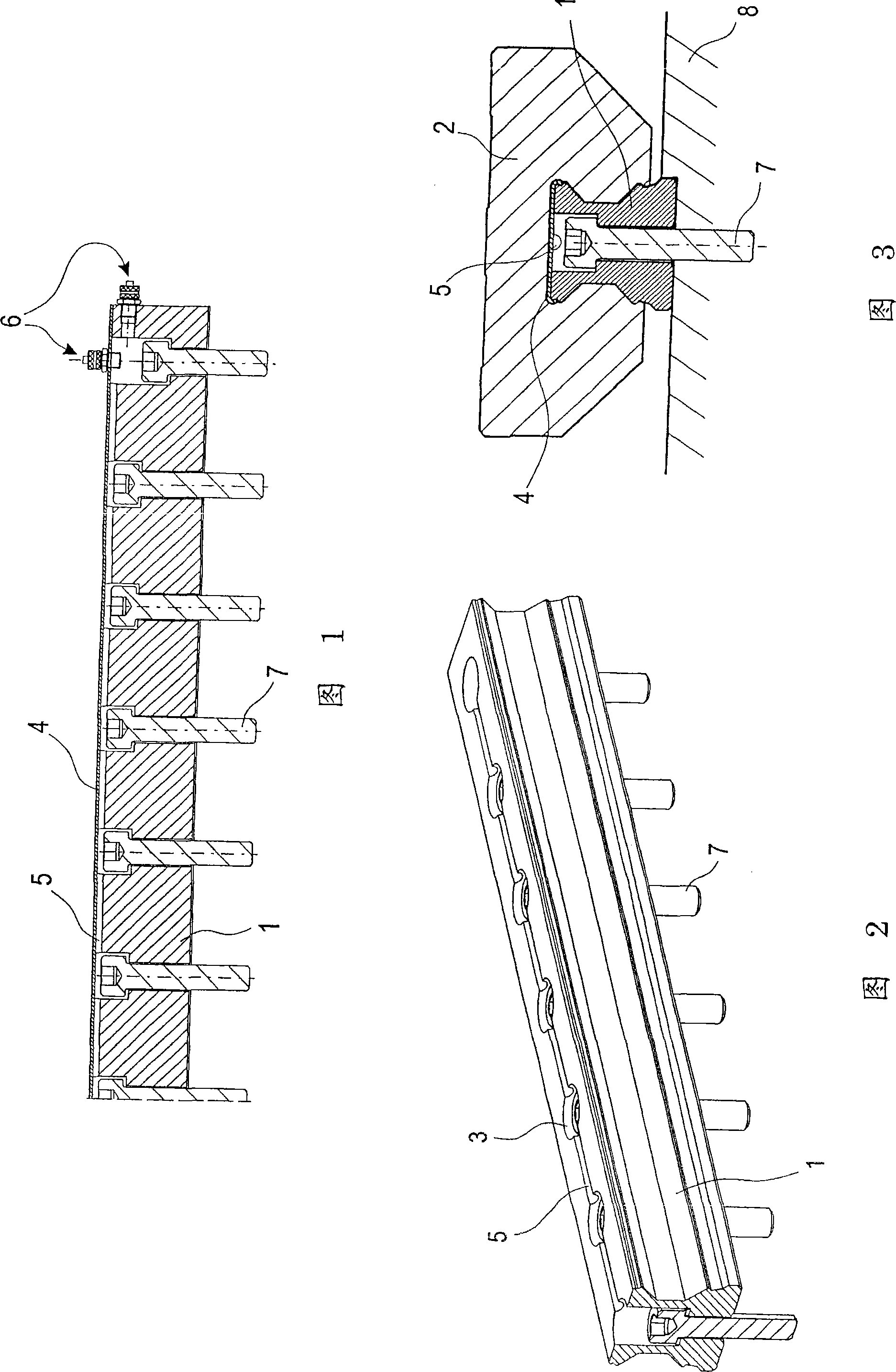
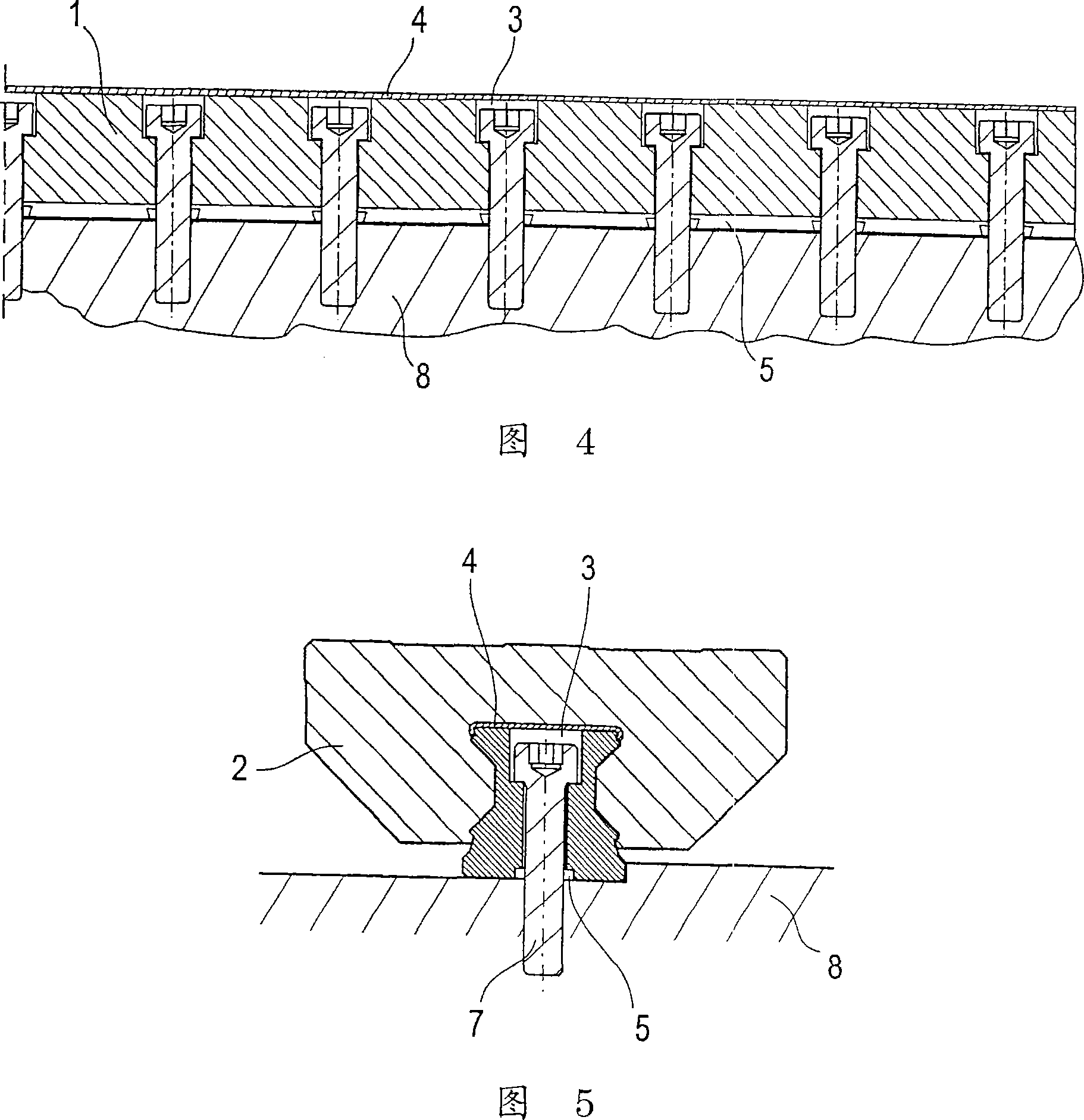
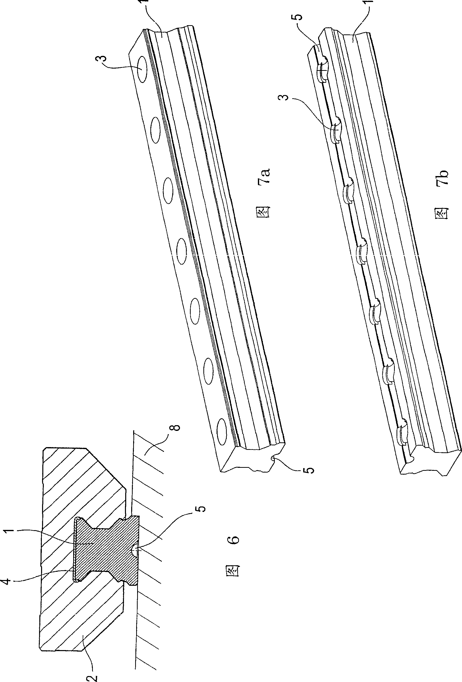
[0045] The linear guide 1 is provided with a protective strip 4 which forms a plane and covers the mounting recess 3 so that no dirt, debris, etc. can penetrate into the gap between the linear guide and the trolley 2 linearly moving on this guide (see image 3 ). In particular, since rolling elements (balls, rollers, etc.) are known from the prior art, in image 3 The illustration of the rolling elements (balls, rollers, etc.) is omitted in the illustration. The same applies to the trolleys and other constructional embodiments of the linear guide rail.

[0046] According to the invention, a coolant groove 5 is provided on the upper side of the linear rail, which groove extends along the length of the rail so as to connect with the mounting recess 3 . Coolant can be supplied or discharged by means of a coolant port 6 mounted to the upper or front side of the linear guide rail. exist figure 1 In the exemplary embodiment shown, for example, the right-hand screw 7 is counters...


PUM


Abstract

The invention relates to a linear guide rail for a linear guide system comprising at least one guide carriage (2) which is movable along the linear guide rail (1) by means of a rolling element, wherein the inventive linear guide rail (1) is characterized in that it is provided with at least one coolant slot (5) extending along at least one part of said linear guide rail (1).

Description

technical field [0001] The invention relates to a linear guide rail for a linear guide system. [0002] Specifically, the present invention relates to a linear guide including a guiding wagon movable along a linear guide by means of rolling members, wherein the linear guide is provided with a mounting recess on its upper side to make the linear guide move by means of screws or the like. Connect to components or modules such as machine tools or machining centers. This mounting recess is covered by a coverband to create a flat surface and prevent debris, dirt or cooling media from penetrating into the gap between the linear guide rail and the trolley. Background technique [0003] In machine tools, guide systems comprising rollers or balls, so-called roller track guides or ball track guides, are often used. The guiding device consists of guide rails and trolleys. The trolley can be moved back and forth on the guide rail using less energy and at the same time with high rigi...

Claims


Application Information

Patent Timeline
Patent Type & Authority Patents(China)
IPC IPC(8): B23Q11/12B23Q1/01F16C29/04
CPCB23Q11/126F16C29/005F16C37/00F16C29/082B23Q1/017F16C29/06F16C29/0633Y10S384/90F16C2322/39
Inventor 荣格尔·勒德斯
Owner P&L合资有限公司
Why Eureka
Try Eureka