Floating wind turbine installation

A technology for wind turbines and equipment, applied in mechanical equipment, wind turbines, wind turbine components, etc., can solve problems such as difficulties, and achieve the effects of large displacement, high strength, and low labor costs

Active Publication Date: 2008-07-09
海维德公司
View PDF0 Cites 10 Cited by
  • Summary
  • Abstract
  • Description
  • Claims
  • Application Information

AI Technical Summary

Problems solved by technology

But finding a technically satisfactory and economically viable solution is difficult

Method used


Image

  • Floating wind turbine installation
  • Floating wind turbine installation
  • Floating wind turbine installation

Examples


Embodiment Construction

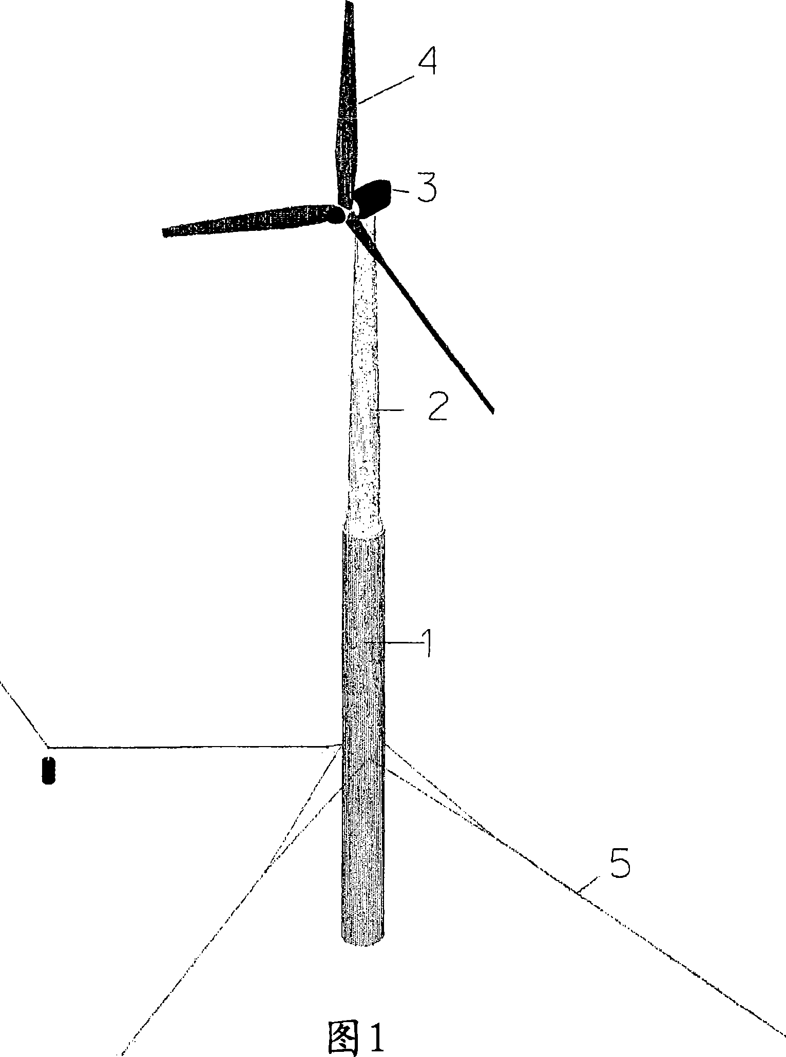
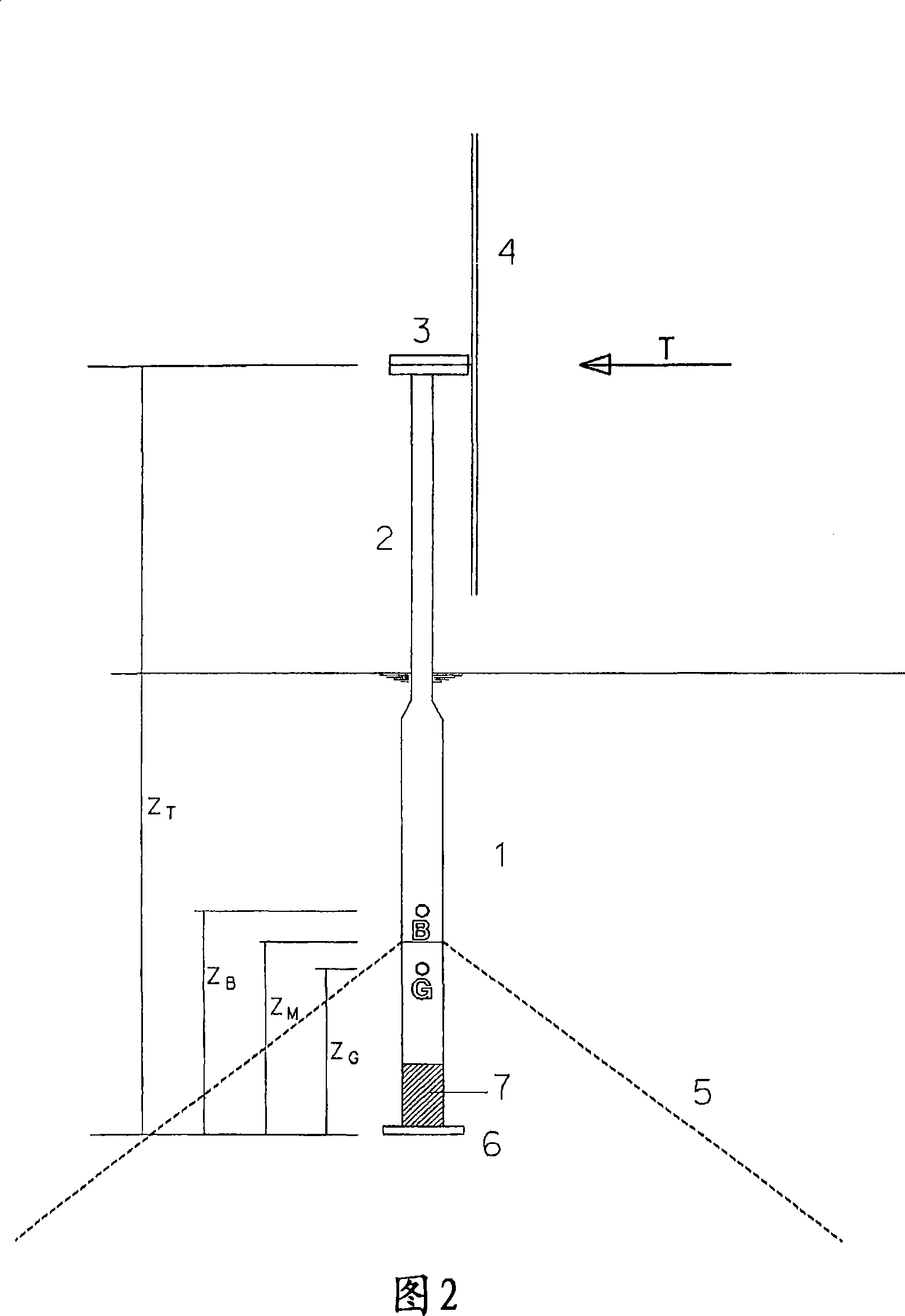
[0017] As shown in Figures 1 and 2, a floating wind turbine installation mainly includes an anchored floating foundation or floating base 1 supporting a tall tower 2 on top of which a turbine is mounted, and a turbine generator housing 3 and a rotor 4, said generator housing 3 enclosing a power generation unit (not shown), and the rotor 4 is arranged to be connected to said power generation unit. The floating base itself, which moves with the waves, is a major negative for the operation of the turbine and the loads placed on the tower. Another factor is that due to limited stability, the wind turbine installation also tends to tip when subjected to wind forces.

[0018] Therefore, the main challenges associated with the development of floating wind turbine installations are to minimize their movement in waves and achieve optimal stability while keeping their costs low.

[0019] Said costs are related to the size of the equipment. Therefore, a general attempt is made to reali...


PUM


Abstract

A method for coordinating wind turbine equipment. The wind turbine installation comprises: a floating base (1); a tower (2) arranged on the floating base; a generator housing (3) mounted on the tower and an anchor line arrangement connected to an anchor or an anchor point on the seabed (5), the generator casing (3) can rotate relative to the wind direction and is equipped with a wind rotor (4). The static heel angle φs_max in the case of full wind load acting on the wind turbine is as low as possible, but preferably less than 8 degrees, and all natural periods of the equipment are outside the periodic range of waves, and the fixed period T05 in pitch (sway T04) is preferably less than 80% of the fixed period T03 in lifting and lowering. Also, the ratio between T03 and T05 is not close to 0.5 or 1.

Description

technical field [0001] The invention relates to a floating wind turbine installation and a method for coordinating hydrostatic and hydrodynamic performance of a wind turbine installation. Such a wind turbine installation comprises a floating base, a tower arranged on the floating base, a generator housing mounted on the tower and an anchor line arrangement connected to an anchor or an anchoring location on the seabed. The generator casing can rotate relative to the wind direction and is equipped with a wind rotor, Background technique [0002] The development of floating anchored wind turbines that can be used at greater depths will greatly increase the ability to access offshore areas to expand wind energy utilization. Existing technology for wind turbines deployed offshore is limited to permanently installing towers at low ground depths, below about 30m. [0003] Permanent installations at depths greater than 30m often create technical problems and are costly. This mean...

Claims


Application Information

Patent Timeline
Patent Type & Authority Applications(China)
IPC IPC(8): F03D11/04F03D1/00B63B21/50B63B
CPCB63B21/50E02B2017/0091F05B2240/93F03D13/25B63B1/048B63B2001/044B63B2035/446Y02E10/72Y02E10/727F03D1/00E02B2017/0095
Inventor 达格芬恩·斯温芬恩·G·尼尔森托尔·D·汉松
Owner 海维德公司
Why Eureka
Try Eureka