Chucking appliance
A clamp and movable clamp technology, applied in the direction of friction-clamped detachable fasteners, clothing, connecting components, etc., can solve the problems of easy rust, increased assembly time, no self-locking function, etc., to achieve a wide range of applications, Easy to use, firm grip
- Summary
- Abstract
- Description
- Claims
- Application Information
AI Technical Summary
Problems solved by technology
Method used
Image

Examples
Embodiment Construction
[0021] The present invention will be further described below in conjunction with accompanying drawing:
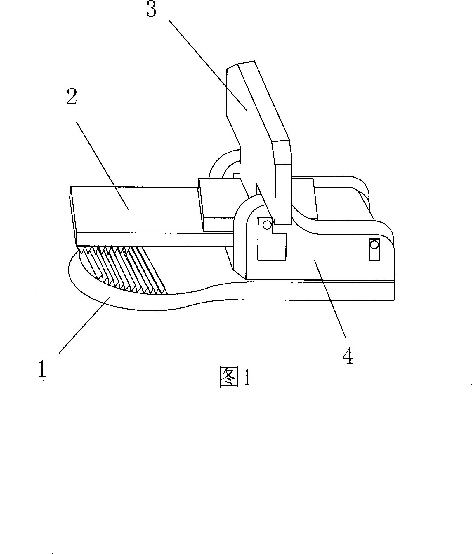
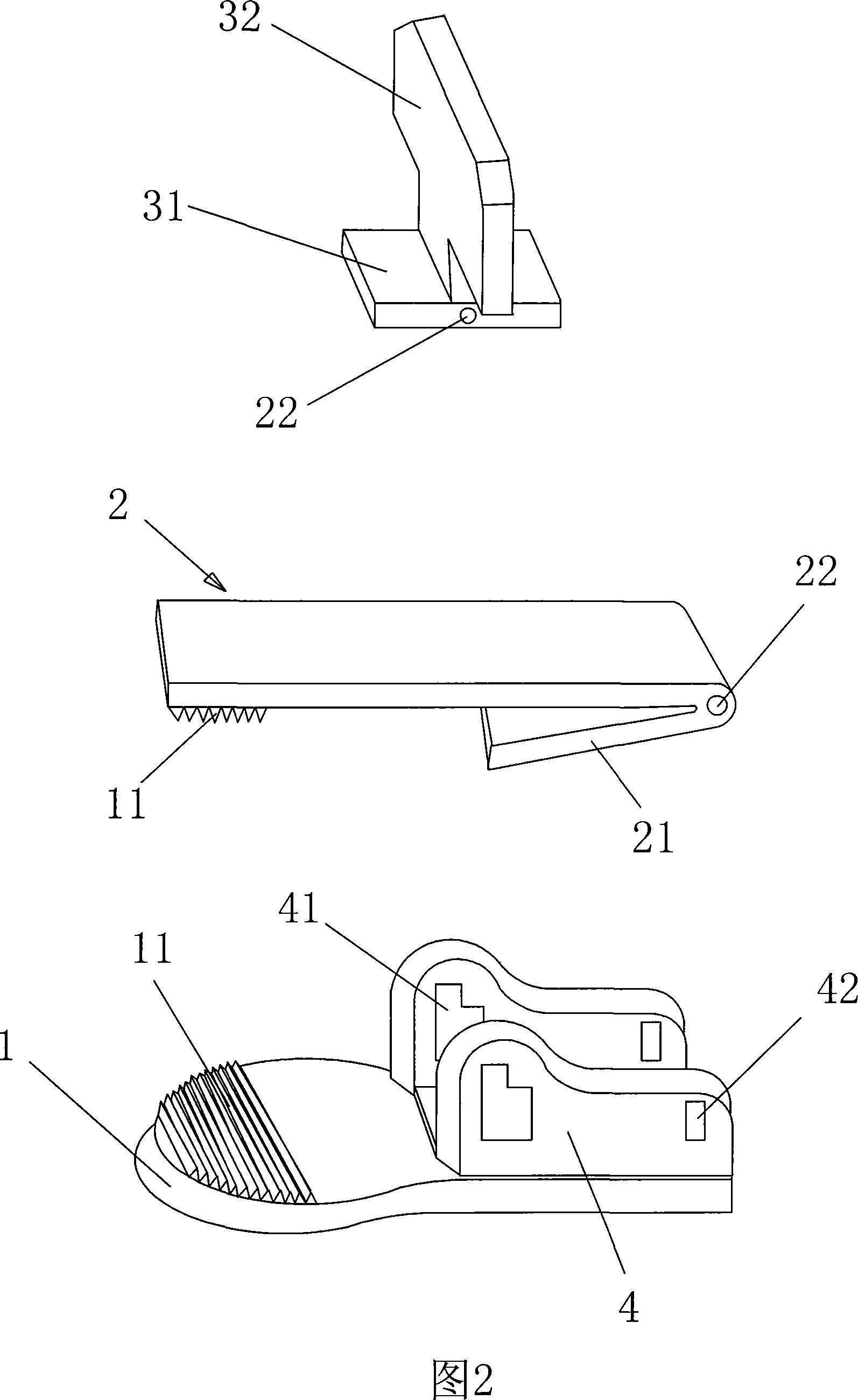
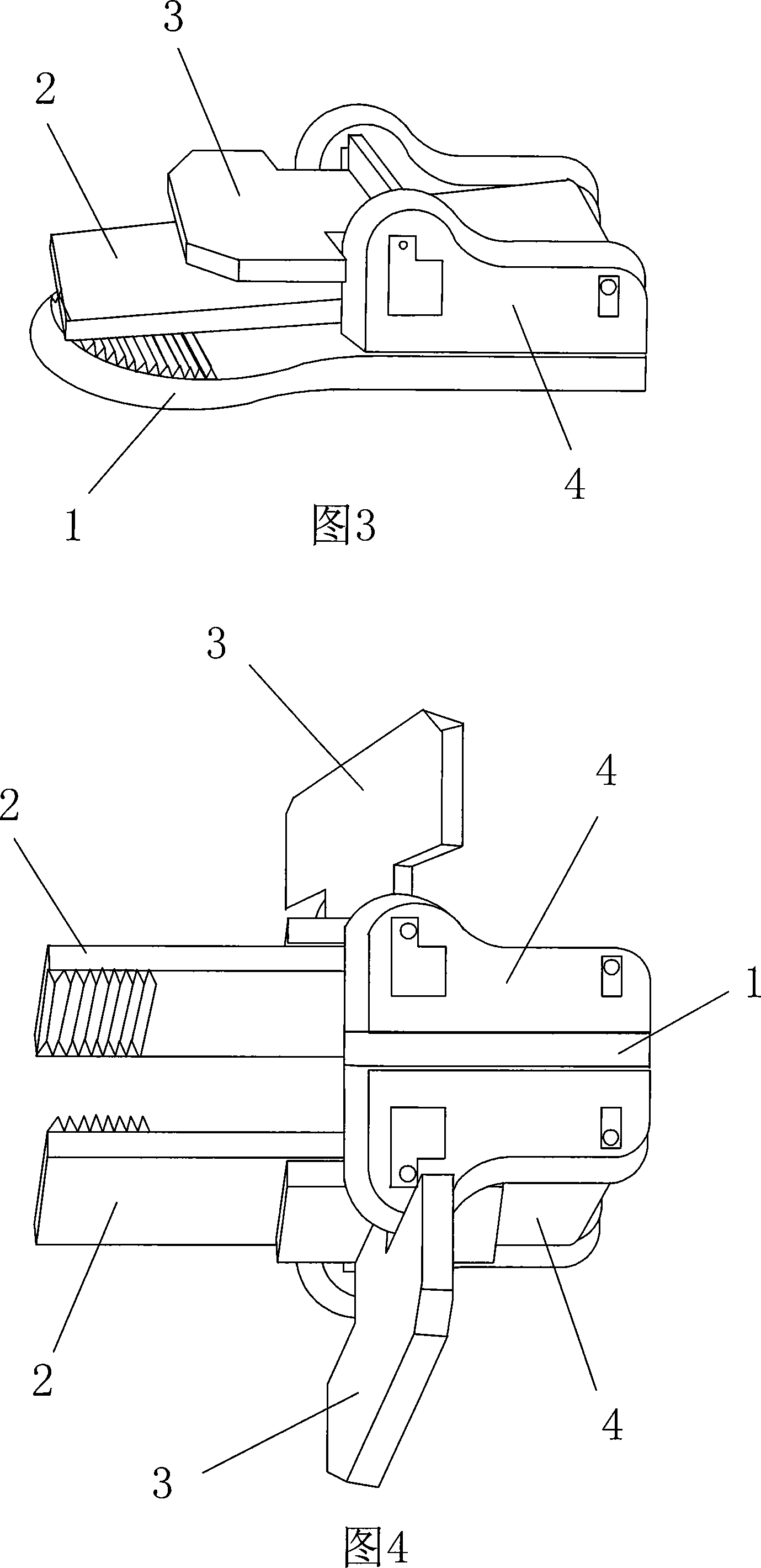
[0022] As shown in the figure, the fixture is divided into single-sided fixture and double-sided fixture. The single-sided fixture is mainly composed of a fixed clamping plate 1, a movable clamping plate 2, and a pressing plate 3. The rear part of the fixed clamping plate 1 is fixed with Two symmetrical brackets 4 have a pressing plate mounting groove 41 and a movable clamping plate mounting groove 42 on the bracket 4; the movable clamping plate 2 is approximately V-shaped in shape, and the V-shaped is composed of one side long and one short side, and the short side Supported on a fixed clamping plate, it has elasticity, and there is a hinge shaft 22 at the top of the V-shaped plate; the pressing plate 3 is composed of a horizontal plate 31 and a vertical plate 32 (approximately T-shaped), and the vertical plate 32 is in the middle of the horizontal plate 31 position, the h...
PUM
 Abstract
Description
Claims
Application Information
 - Generate Ideas
- Intellectual Property
- Life Sciences
- Materials
- Tech Scout
- Unparalleled Data Quality
- Higher Quality Content
- 60% Fewer Hallucinations
Browse by: Latest US Patents, China's latest patents, Technical Efficacy Thesaurus, Application Domain, Technology Topic, Popular Technical Reports.
© 2025 PatSnap. All rights reserved.Legal|Privacy policy|Modern Slavery Act Transparency Statement|Sitemap|About US| Contact US: help@patsnap.com