B image equalization method and system structure based on two-dimension analysis

A technology of two-dimensional analysis and equalization method, applied in the medical field, can solve the problems of equalization and inability to achieve image brightness, and achieve the effect of simplifying user operations

Active Publication Date: 2008-07-16
SHENZHEN MINDRAY BIO MEDICAL ELECTRONICS CO LTD
View PDF5 Cites 30 Cited by
  • Summary
  • Abstract
  • Description
  • Claims
  • Application Information

AI Technical Summary

Problems solved by technology

Use the traditional "Digital time gain compensation" or DTGC module to compensate the brightness. The compensation coefficient is only related to the depth, because the D A ,D B ,D C The corresponding depths of the three points are the same, and the coefficients used for compensation must also be the same. Their own echo amplitudes are quite different, so the amplitudes of the results after compensation are also quite different, and the purpose of equalizing the image brightness through compensation cannot be achieved.

Method used


Image

  • B image equalization method and system structure based on two-dimension analysis
  • B image equalization method and system structure based on two-dimension analysis
  • B image equalization method and system structure based on two-dimension analysis

Examples


Embodiment Construction

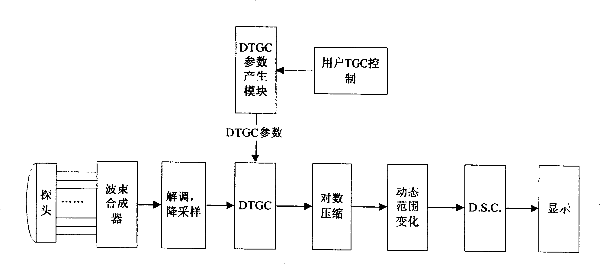
[0018] First, a conventional DTGC calculation method will be described. figure 2 It is a schematic block diagram of a conventional B-type ultrasonic imaging system, and its transmitting part is not drawn because it has little to do with the present invention. The conventional B-type imaging process is usually: the probe emits pulses, and the receiving array elements receive echoes, which are amplified, A / D converted, and added in the beamformer with different delays to obtain radio frequency data. The RF data undergoes envelope detection and down-sampling, DTGC, logarithmic compression, and dynamic range change, and at the same time enters "digital scan conversion" that is D.S.C, and the result of D.S.C is displayed on the screen, that is, B-type image.

[0019] In most systems, DTGC refers to giving different gains to the input data along the depth direction, that is, according to time, in order to make the brightness of the image displayed on the screen more uniform. Gener...


PUM


Abstract

The invention provides a B image balancing method and a system structure based on two-dimensional analysis relating to a data processing technology of ultrasonic B image in medical field. A data buffer region is additionally arranged in an ultrasonic imaging system to store demodulated and desampled data and write the data into 'digital time gain compensation', namely a DTGC parameter generating module, and then the DTGC parameters output by the module are written into a DTGC module; the DTGC module compensates the data of each beam or every adjacent plurality of beams of receiving scanning lines with different DTGC parameters PDM[i][j], wherein, the PDM[i][j] is a two-dimensional array and the value is different for different receiving scanning lines. Compared with the prior art, the method and the system structure have the beneficial effects that the two-dimensional DTGC parameters overcome the defect that the lateral balancing of the image cannot be solved by one-dimensional DTGC parameters only related to depth; in addition, the two-dimensional DTGC parameters full automatically analyze and need no customer involvement, thereby simplifying customer operation.

Description

technical field [0001] The present invention relates to ultrasonic detection technology in the medical field, in particular to B image data processing technology, especially to a B image equalization method and system structure based on two-dimensional analysis. Background technique [0002] In the prior art, when using B-mode imaging for ultrasonic diagnosis, the diagnostician mainly adjusts the TGC (time gain compensation) manually or uses the system to automatically adjust the TGC parameters, that is, the automatic gain compensation technology or one-key optimization, so that the overall brightness of the image is balanced. . TGC gives different gains to different depth regions of the image, and through this gain compensation, the brightness of the parts representing uniform tissues in the image is basically balanced. There is an assumption in such compensation, that is, the attenuation along the depth direction of the ultrasonic echo corresponding to all receiving lines...

Claims


Application Information

Patent Timeline
Patent Type & Authority Applications(China)
IPC IPC(8): A61B8/14G06T5/00
Inventor 蒋勇
Owner SHENZHEN MINDRAY BIO MEDICAL ELECTRONICS CO LTD
Why Eureka
Try Eureka