Vehicle exhaust system structure

An exhaust system, vehicle technology, applied in exhaust devices, vehicle components, air quality improvement and other directions

Inactive Publication Date: 2008-07-16
TOYOTA JIDOSHA KK
View PDF2 Cites 8 Cited by
  • Summary
  • Abstract
  • Description
  • Claims
  • Application Information

AI Technical Summary

Problems solved by technology

[0003] However, in the prior art described above, there is concern that a large force is applied to the bent portion of the exhaust pipe when an exhaust heat recovery member having a large mass is arranged along the exhaust system, so there is still improvement in this aspect Space

Method used


Image

  • Vehicle exhaust system structure
  • Vehicle exhaust system structure
  • Vehicle exhaust system structure

Examples


Embodiment Construction

[0008] Hereinafter, examples of exemplary embodiments of the present invention will be described in detail with reference to the accompanying drawings.

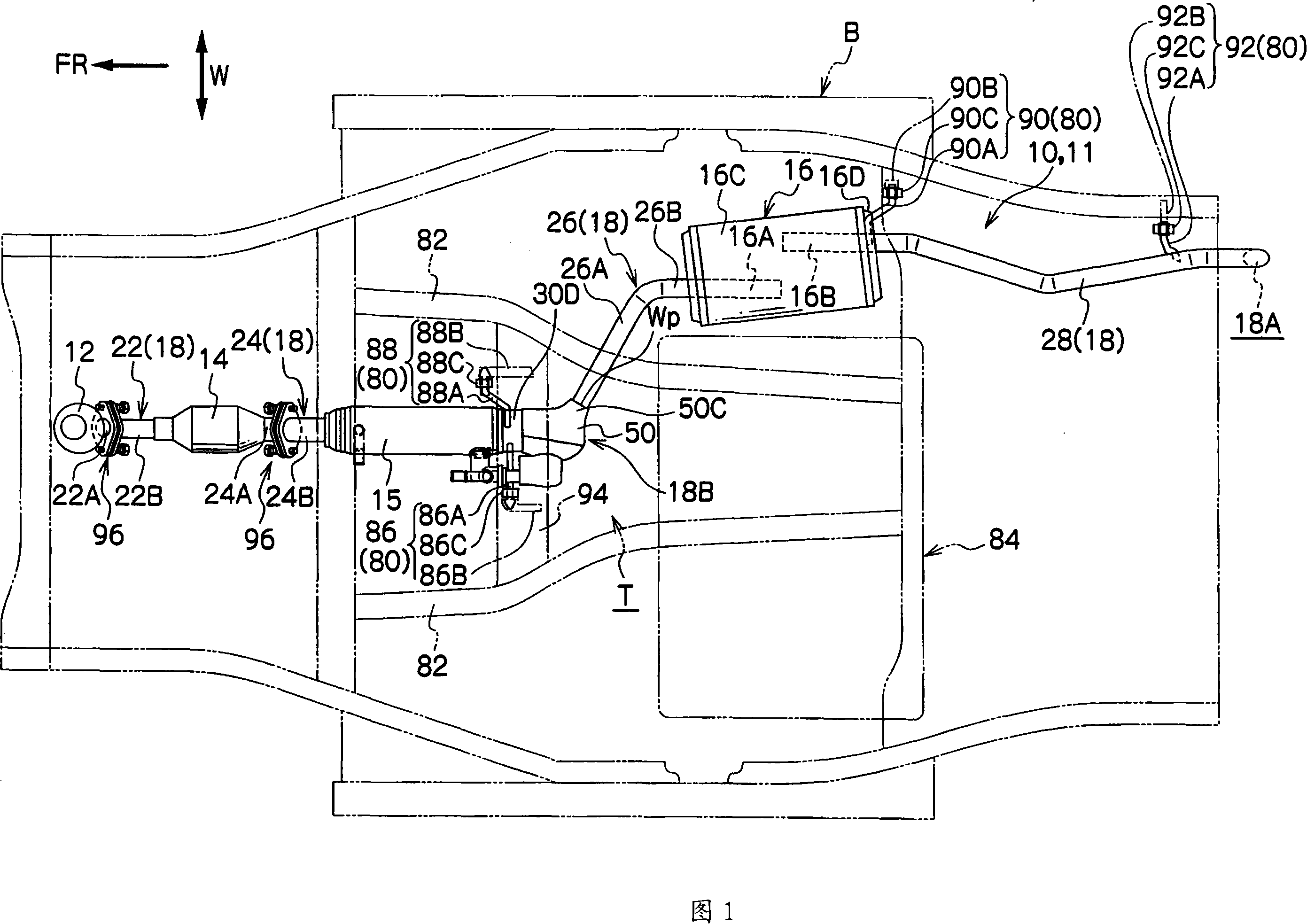
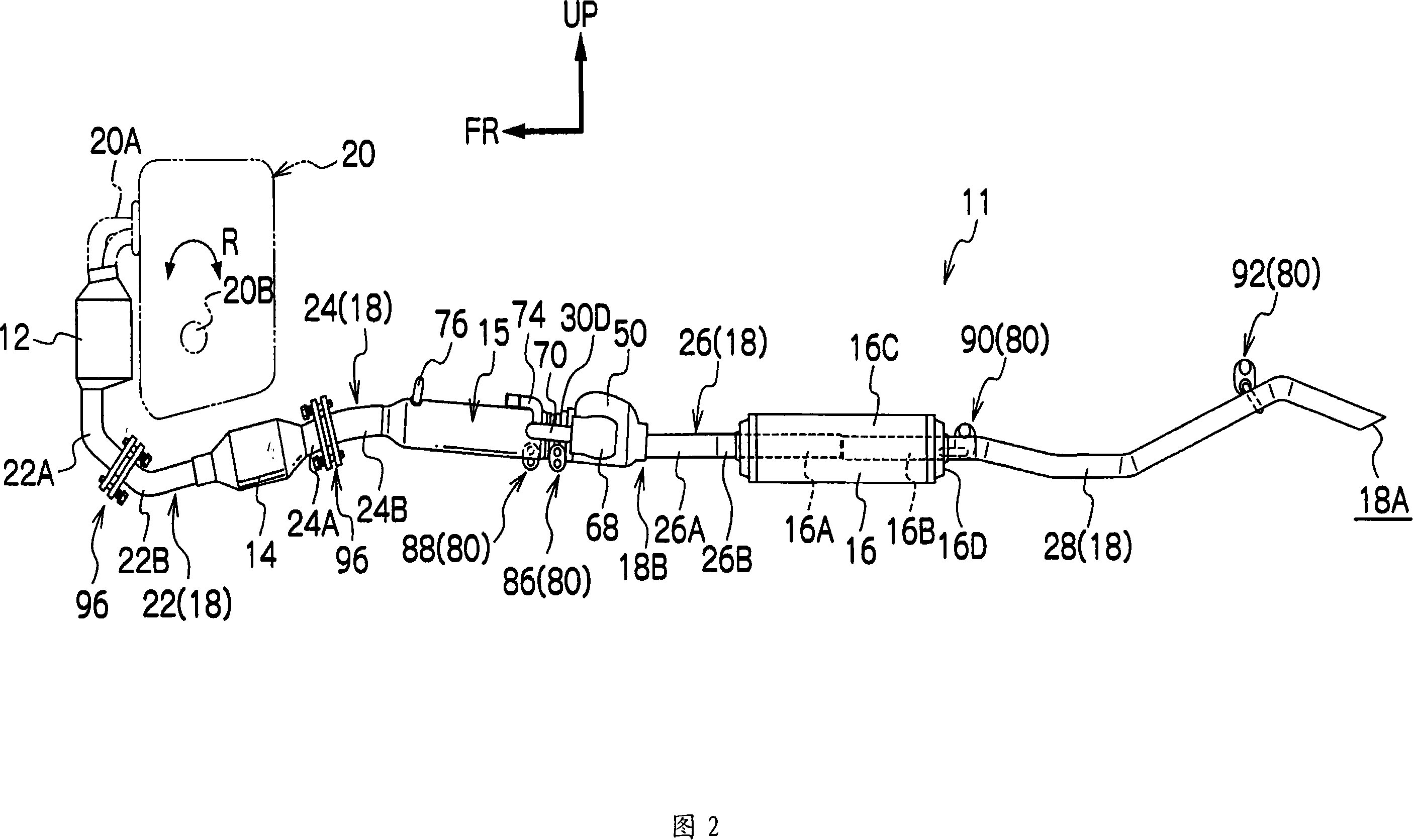
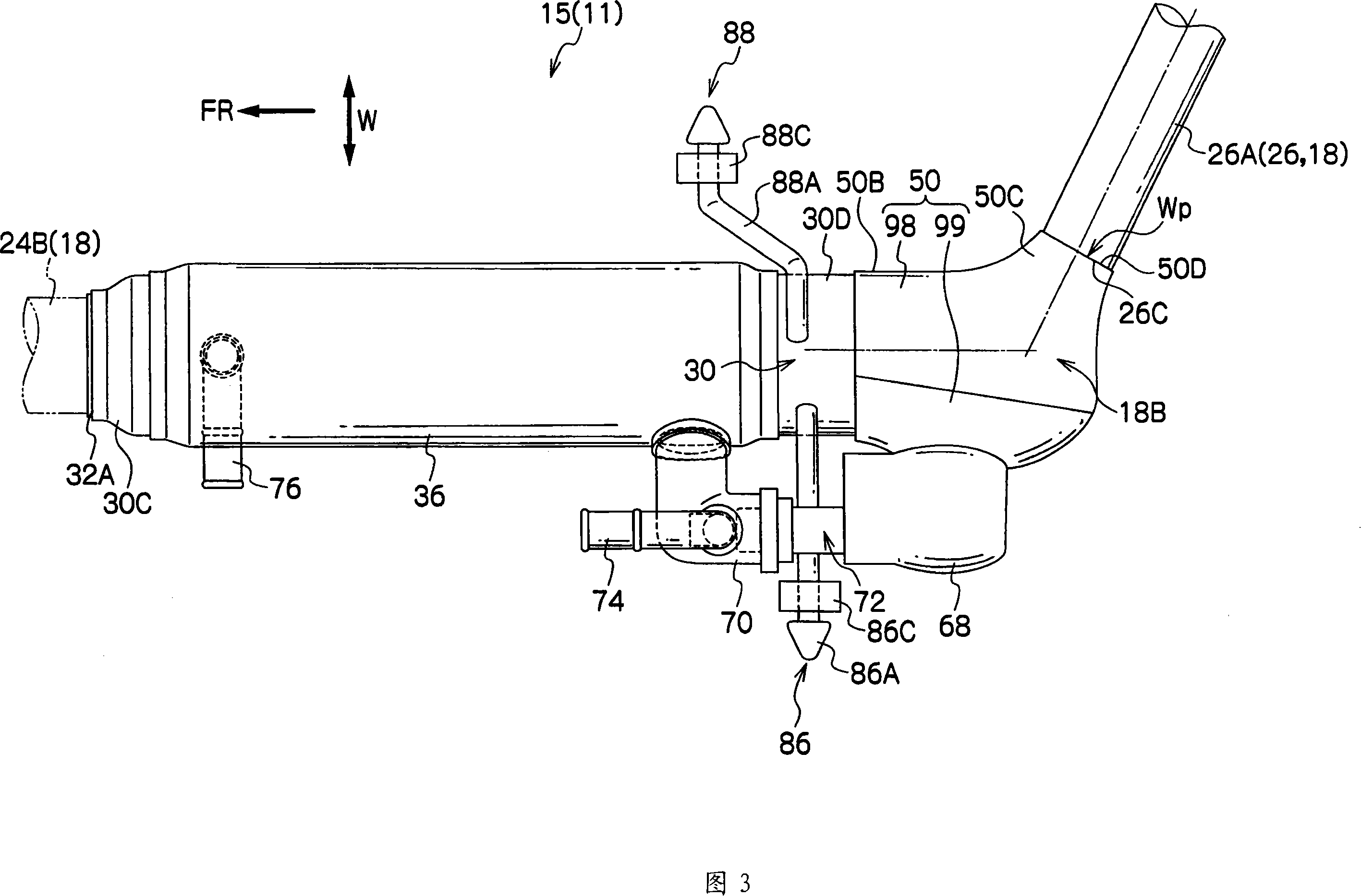
[0009] First, the overall structure of the exhaust system 11 to which the vehicle exhaust system structure 10 is applied will be schematically explained, next, the exhaust system heat exchanger 15 constituting the vehicle exhaust system structure 10 will be explained, and then , the support structure of the exhaust system 11 relative to the vehicle body, which constitutes the main part of the present invention in the vehicle exhaust system structure 10, will be described. Note that in the following description, when terms such as upstream and downstream are simply used, they mean upstream and downstream in the exhaust gas flow direction. In addition, arrow FR, arrow UP and arrow W shown in each drawing represent the front side (traveling direction) in the vehicle front-rear direction and the upper side in the vertical directi...


PUM


Abstract

A vehicle exhaust system structure is obtained which can protect well a bend portion of an exhaust pipe. A vehicle exhaust system structure is intended to discharge exhaust gases of a front-engine front-drive vehicle with a transverse engine from a rear part of a vehicle body and is applied to an exhaust system which is configured such that a first catalytic converter, a second catalytic converter, an exhaust system heat exchanger and a muffler are disposed sequentially in that order from an upstream side in an exhaust gas flow direction. In the exhaust system, a heat exchanger to muffler exhaust pipe which connects the exhaust system heat exchanger to the muffler has an inclined portion, and a portion of the exhaust system which lies further rearwards than the exhaust system heat exchanger is suspended from the vehicle body by a suspension unit. Provided on a catalytic converter to heat exchanger exhaust pipe which connects the second catalytic converter to the exhaust system heat exchanger is a ball joint which permits a relative displacement between the second catalytic converter and the exhaust system heat exchanger.

Description

technical field [0001] The present invention relates to a vehicle exhaust system structure for an internal combustion engine mounted transversely at the front of a vehicle body of, for example, a front-engine front-wheel drive vehicle, and more particularly to an exhaust heat recovery member including exhaust heat recovery means for recovering exhaust heat Vehicle exhaust system structure. Background technique [0002] For example, in an exhaust system connected to a transverse internal combustion engine, as disclosed in Japanese Patent Application Laid-Open Nos. 10-196358 and 2004-190610 (JP-A), in which a catalytic converter, a secondary muffler, and a primary The muffler is provided in the above order just from the upstream side of the exhaust gas flow direction, there is a known structure in which a bent portion is provided on the exhaust pipe connecting the sub muffler to the main muffler, and ball joints are respectively provided Upstream of the catalytic converter in...

Claims


Application Information

Patent Timeline
Patent Type & Authority Applications(China)
IPC IPC(8): F01N7/08B60K13/04F01N3/24F01N5/02F01N13/00F01N13/08F01N99/00
CPCF01N13/009F01N13/08B60K13/04F01N2013/023F01N13/1811F01N13/0093F01N13/02F01N13/1822F01N3/2885F01N13/1816Y02A50/20F01N3/24F01N3/28
Inventor 马渕知树西野寿
Owner TOYOTA JIDOSHA KK
Why Eureka
Try Eureka