Axial fan for cooling electronic component

A technology of electronic components and axial flow fans, applied to pump components, components of pumping devices for elastic fluids, instruments, etc., can solve problems such as limited cooling performance

Inactive Publication Date: 2008-07-16
XI AN JIAOTONG UNIV
View PDF0 Cites 5 Cited by
  • Summary
  • Abstract
  • Description
  • Claims
  • Application Information

AI Technical Summary

Problems solved by technology

Therefore, the traditional axial fan has great limitations i

Method used


Image

  • Axial fan for cooling electronic component
  • Axial fan for cooling electronic component

Examples


Embodiment Construction

[0008] The present invention will be described in further detail below in conjunction with the accompanying drawings.

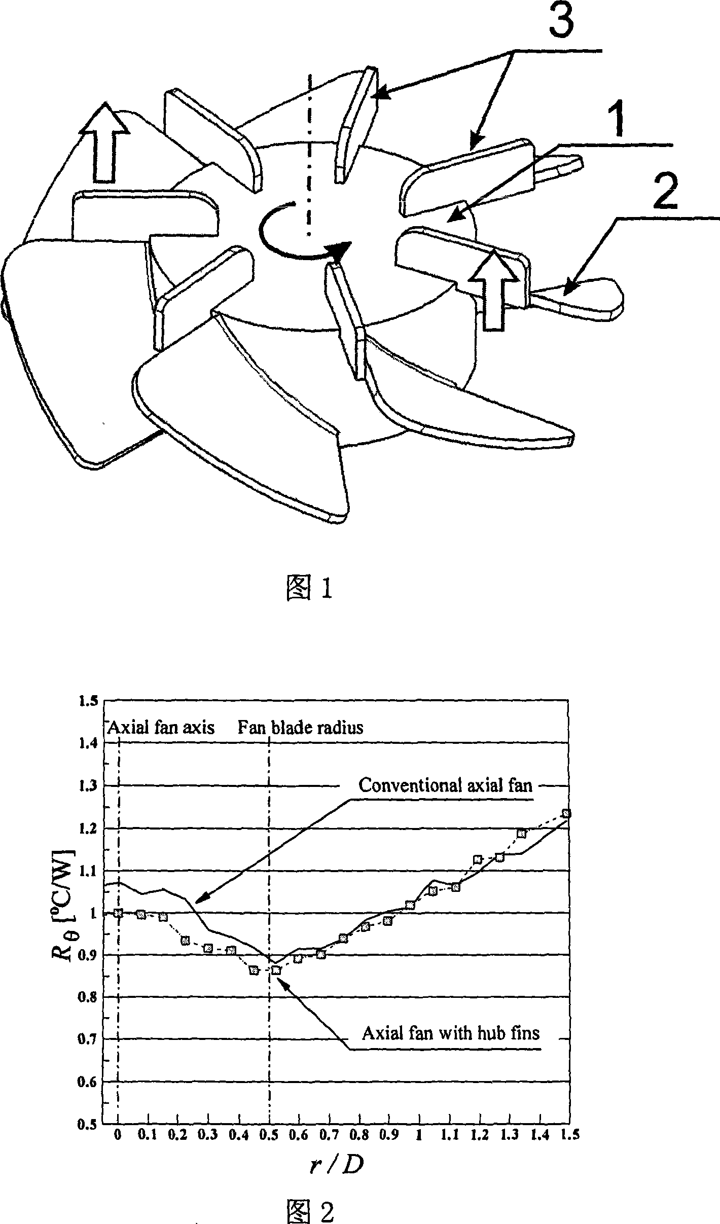
[0009] Referring to Fig. 1, the present invention includes a hub 1 located at the center of the fan main body and a main blade 2 fixed on the outside of the hub 1, and a square attachment blade 3 is also arranged on the hub 1, the attachment blade 3 is 16 mm long, 6 mm wide, and thick. 1.6mm. Except for the edges attached to both sides of the hub 1 and the trailing edge of the main blade 2, the other sides of the attached blade 3 are trimmed to be as smooth as possible. The length of the attached blade 3 with a total length of 16 mm on the central hub 1 is 10 mm, and the length on the trailing edge of the main blade 3 is 6 mm. Since the attached blades 3 are arranged on the central hub 1, the weight of the present invention is increased by 15%. Since the DC voltage driving the axial fan remains unchanged (12DCV), the speed of the fan is correspondingly redu...


PUM

PropertyMeasurementUnit
Lengthaaaaaaaaaa

Abstract

The invention provides an axial flow fan used for the heat dissipation of an electronic element, comprising a hub which is arranged at the center of a fan mainbody and main vanes which are fixed at the external side of the hub; the hub is also provided with attached vanes; one end of the attached vane is fixedly connected with the hub and the other end thereof is fixedly connected with the rear edge of the main vanes. The invention improves the heat exchange condition at the downstream area of the axial flow motor by adding a small vane on the central hub of the fan, thus greatly improving the efficiency of a radiator. Compared with a traditional fan, the central hub of the fan is provided with attached vanes, and the integration cooling performance of the impact baseplate of the invention is improved by about 10% compared with the traditional axial flow fan under the same input power.

Description

technical field [0001] The invention relates to an axial flow fan, in particular to the technical field of an axial flow fan applied to heat dissipation of electronic components. technical background [0002] Axial flow fans have stable and reliable performance and price advantages, and have been widely used in cooling systems of electronic equipment for a long time, such as: central processing unit (CPU) cooling systems, generally composed of axial flow fans and aluminum fins The heat sink acts as a heat sink unit consisting of the extended surface of the CPU. A finned heat sink structure is installed on the upper surface of the heat source (CPU). The substrate connected to the CPU (the CPU occupies approximately 13% of the entire substrate area) usually uses materials with a high heat transfer coefficient, such as aluminum and copper. On the air side, the axial flow fan drives the cooling medium (air) into the narrow channel of the finned radiator, and the plane of the f...

Claims


Application Information

Patent Timeline
IPC IPC(8): F04D29/38F04D25/08G06F1/20
Inventor 金东范卢天健
Owner XI AN JIAOTONG UNIV
Why Eureka
Try Eureka