
Detachable direct-current motor

A DC motor, detachable technology, applied in the field of experimental devices, can solve the problems of non-detachable, unsuitable for grouping experimental devices, high cost, etc., and achieve the effect of simple structure, low cost and convenient operation

Inactive Publication Date: 2008-07-16
姚成兴
View PDF0 Cites 6 Cited by
  • Summary
  • Abstract
  • Description
  • Claims
  • Application Information

AI Technical Summary

Problems solved by technology

[0004] 1. High cost
[0005] 2. Coils, commutators, etc. are finished products and cannot be disassembled
[0006] Based on the above shortcomings, the existing demonstration experiment DC motor is not suitable for changing it into a group experiment device for students

Method used


Image

  • Detachable direct-current motor

Examples


Embodiment

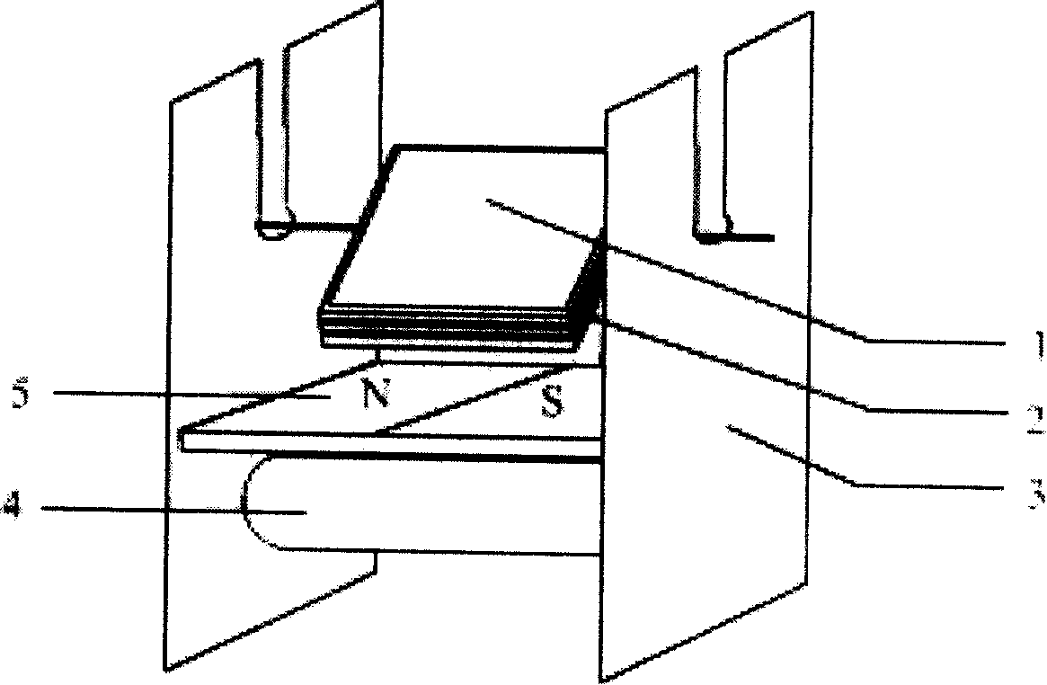
[0021] 1. Wind an enameled wire with a diameter of 1mm and a length of 428mm on a foam plastic of 38mm×25mm×15mm, lead out a lead wire with a length of 25mm at each end, and scrape off all the paint on one of the lead wires, and remove half of the other lead wire along the axis patent leather.

[0022] 2. Punch a hole with a diameter of 3mm at a distance of 20mm from the top of two iron plates of 85mm×30mm×2mm, and open a slot with a width of 2mm from the hole to the top.

[0023] 3. Each end of the magnet absorbs a stator plate, and the bottom of the magnet absorbs a AA battery.

[0024] 4. Put the two lead wires of the rotor into the two round holes through the groove of the stator plate. At this time, the circuit of the rotor is connected, and it is rotated by the magnetic torque.


PUM


Abstract

The invention discloses a detachable DC motor experimental facility which comprises a rotor (an enamelled wire, a rotor core) stator board, a magnet and a battery. The stator board and the battery are directly pulled on the magnet, thereby saving a circuit and a battery box. The invention has the advantages that the structure is simple, the installation is convenient, the cost is low, and the invention is applicable to grouping experiments for students and has obvious effect compared with similar demonstration experiments, etc.

Description

Technical field: [0001] The invention relates to an experimental device, in particular to a DC motor used in high school physics teaching. Background technique: [0002] In high school physics teaching, "DC motor" is both an important teaching content and a difficult teaching content, and the best way to break through this difficulty is to let every student assemble a small motor by himself. However, at present, there is no equipment suitable for students to conduct group experiments in China, only the devices used by teachers to demonstrate experiments. [0003] Existing demonstration experiment electric motor has following shortcoming: [0004] 1. High cost. [0005] 2. Coils, commutators, etc. are finished products and cannot be disassembled. [0006] Based on the above shortcomings, the existing demonstration experiment DC motor is not suitable for changing it into a group experiment device for students. Invention content: [0007] In view of the above situation, t...

Claims


Application Information

Patent Timeline
Patent Type & Authority Applications(China)
IPC IPC(8): G09B23/18
Inventor 姚成兴
Owner 姚成兴
Learn More