
State control signal testing device

A technology of signal testing and state control, applied in the direction of monitoring/monitoring/test arrangement, selection device, radio/inductive link selection arrangement, etc., which can solve the problems of insufficient and inappropriate register resources of programmable devices, and achieve the purpose of increasing the number of boards Quantity, the effect of improving the efficiency of production testing

Inactive Publication Date: 2008-07-16
蒙路遥 +4
View PDF0 Cites 13 Cited by
  • Summary
  • Abstract
  • Description
  • Claims
  • Application Information

AI Technical Summary

Problems solved by technology

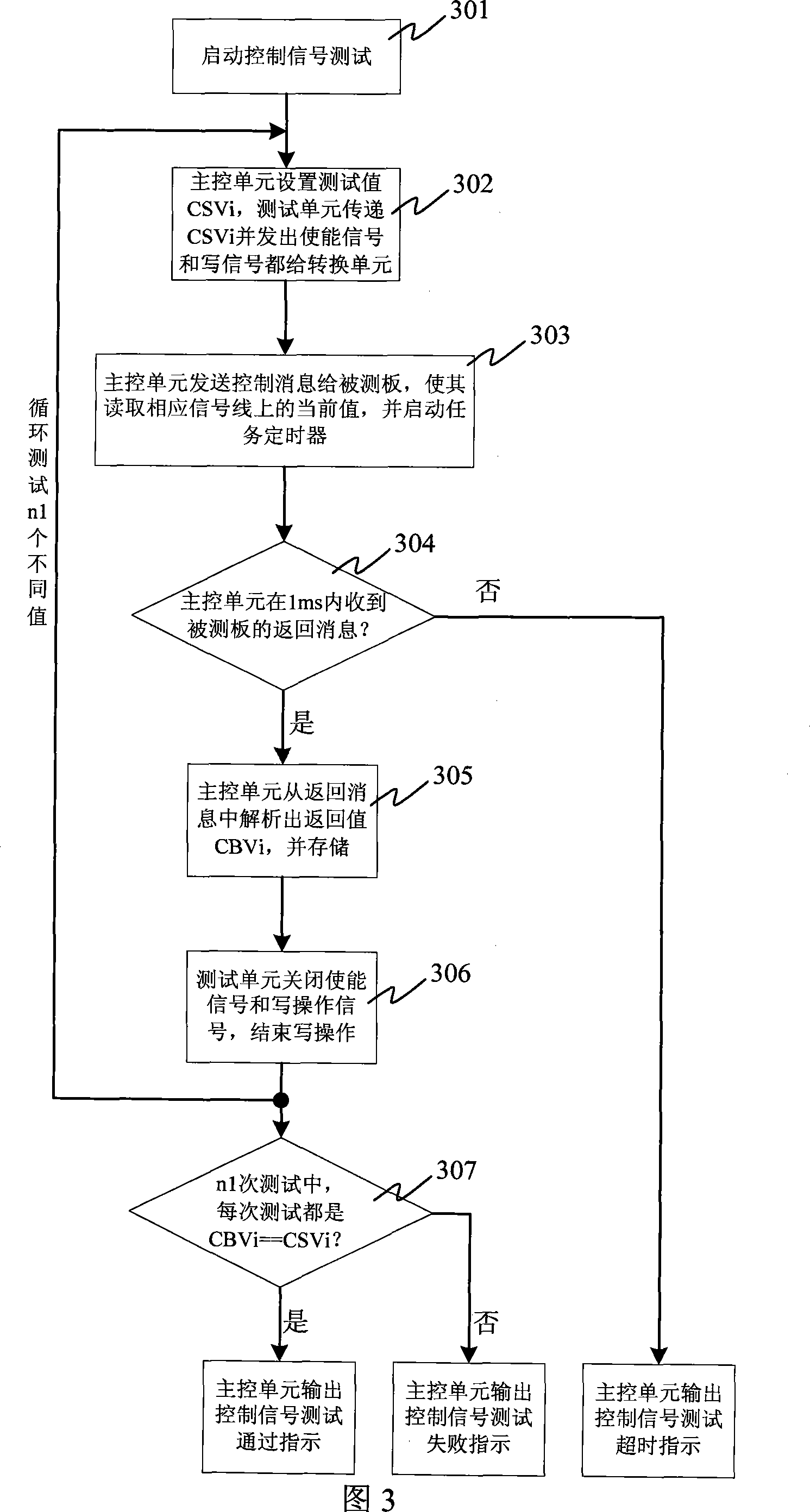
[0004] The test of the state control signal is a relatively simple but necessary test item with a large quantity. Since the test occupies a lot of pins, but the register resources of the programmable device occupied are relatively small, so a large-capacity programmable device is selected or reduced. The method of testing the number of single boards is not suitable

Method used


Image

  • State control signal testing device
  • State control signal testing device
  • State control signal testing device

Examples


Embodiment Construction

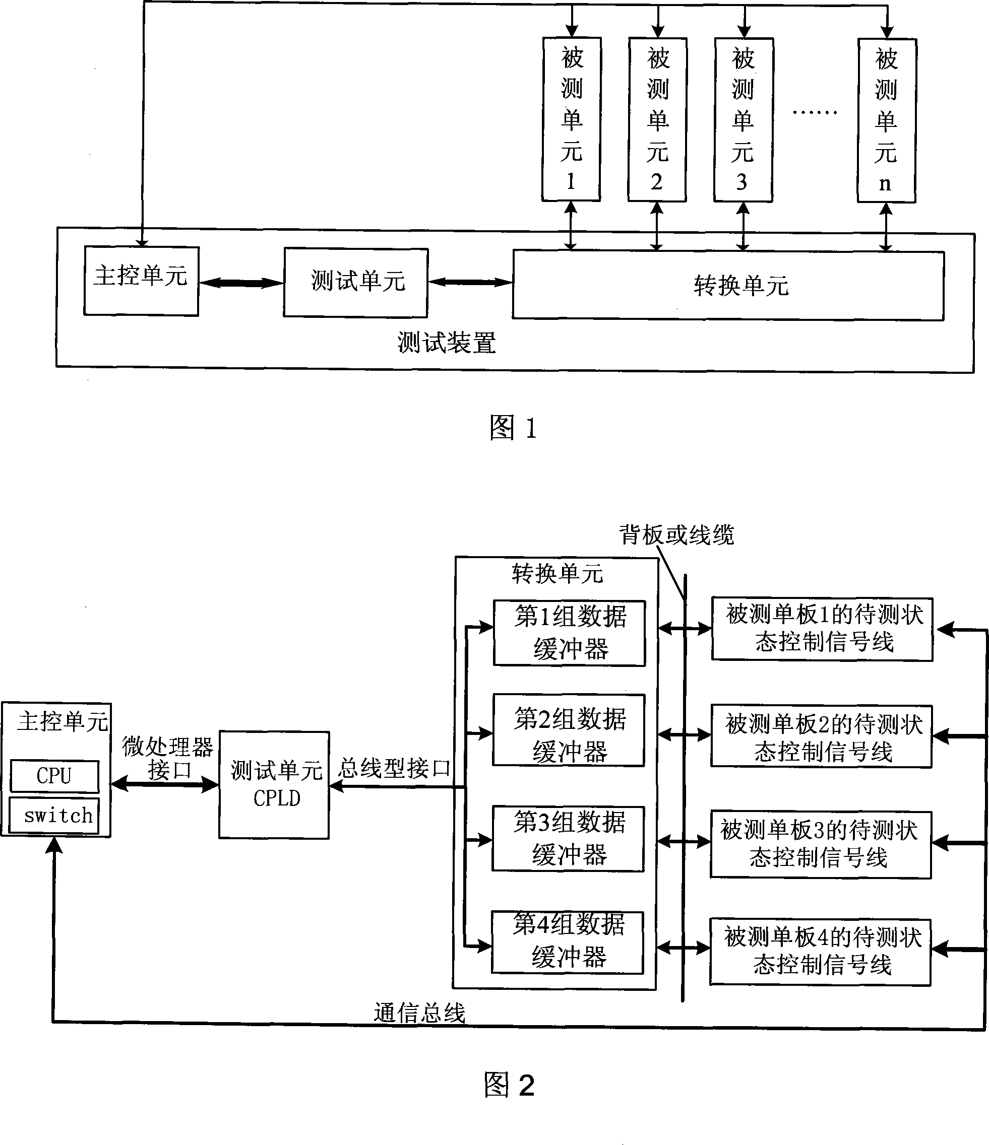
[0038] As shown in Figure 1, the state control signal test device of the present invention is used to test whether the state control signal functions of a plurality of units under test are normal, and the device includes a main control unit, a test unit, and a conversion unit, wherein:

[0039] Main control unit: mainly to set the test value to the test unit, or obtain the test value from the test unit. And compare the set or obtained test value with the test value fed back by the unit under test by means of message transmission with the unit under test, and then output the test result;

[0040] Test unit: It mainly controls the working state of the conversion unit, and transmits the test value set by the main control unit to the conversion unit, or obtains and stores the test value from the conversion unit.

[0041] Conversion unit: mainly converts the signal line of the control status of the unit under test into a bus-type interface signal line, and receives or sends the tes...


PUM


Abstract

The invention provides a status control signal testing device which is used for testing the status control signal function of a tested unit. The device comprises a main control unit, a testing unit and a conversion unit, wherein the main control unit is used for setting up a test value for the testing unit or obtaining the test value from the testing unit, comparing the set or obtained test value with the test value fed back by information transmission in the tested unit for consistency and further outputting a test result; the testing unit is used for controlling the working status of the conversion unit and relaying the test value set by the main control unit to the conversion unit or obtaining the test value from the conversion unit and storing the test value; the conversion unit is used for converting the control status signal line to be tested of the tested unit into a bus type interface signal line and receiving or sending out the test value of the tested unit. The testing device provided by the invention can make use of the pin resources of a programmable device effectively and improve production testing efficiency.

Description

technical field [0001] The invention relates to a single-board hardware function test system, in particular to a device for testing whether the function of a state control signal is normal. Background technique [0002] At present, in the field of single-board hardware function testing, the main test board is mainly used to test the signal function of the board under test through the backplane and cables. The functional test of the state control signal on the single board under test is either a loopback self-test of the tested board, or a corresponding functional test by connecting the signal to a programmable device on the test board at the same time. During the loopback test of the tested board, the result after the self-test is output directly; The registers corresponding to the state control signals are set in the test board, and the main test board controls the registers of the programmable logic through the message transmission between the board and the tested board, ...

Claims


Application Information

Patent Timeline
Patent Type & Authority Applications(China)
IPC IPC(8): H04Q7/34H04M3/22
Inventor 王红展张文国
Owner 蒙路遥
Learn More