Inverted type machine tool

An inverted, machine tool technology, applied in the direction of boring/drilling, metal processing equipment, drilling/drilling equipment, etc., can solve the difficulty of machine tool transportation, movement and installation, increase transportation costs, increase machine tool material costs and processing Cost and other issues

Inactive Publication Date: 2008-07-23
梁刚
View PDF0 Cites 17 Cited by
  • Summary
  • Abstract
  • Description
  • Claims
  • Application Information

AI Technical Summary

Problems solved by technology

[0003] (1) Since the workpiece at the workbench is processed from top to bottom, the reference plane of the workpiece must face the reference plane of the tooling from the bottom up when clamping, which is not conducive to the alignment of the reference plane of the workpiece and the reference plane of the tooling. The clamping time is long and the coincidence between the workpiece datum plane and the tooling datum plane is low, which also reduces the machining accuracy
[0004] (2) The power head is located above the workben

Method used


Image

  • Inverted type machine tool
  • Inverted type machine tool

Examples


Example Embodiment

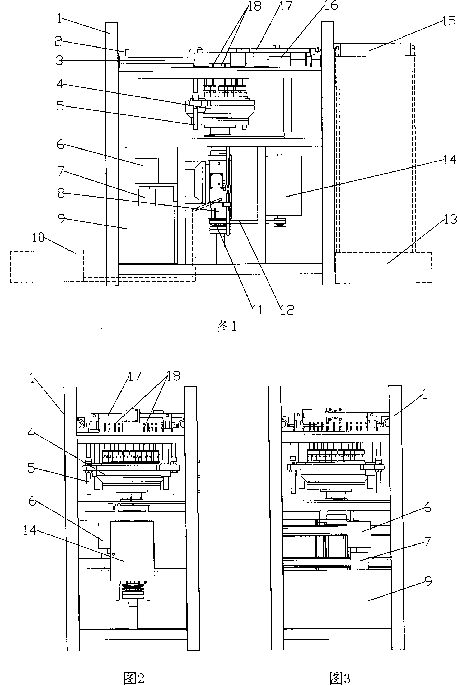
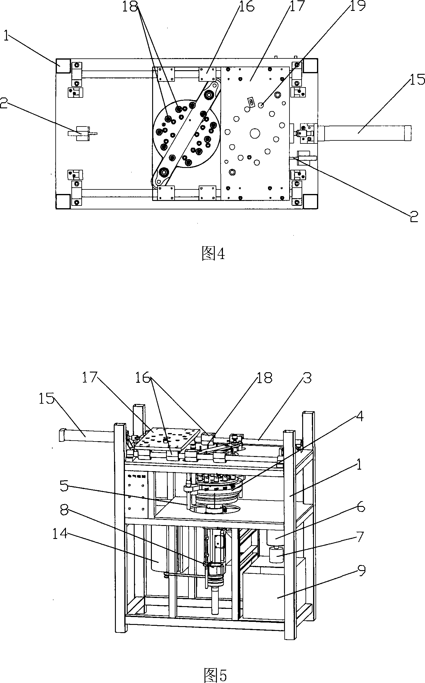
[0013] The inverted machine tool of the present invention will be further described below with reference to the accompanying drawings and specific embodiments to help understand the content of the present invention.

[0014] As shown in Figures 1 to 5, it is an inverted multi-head drilling machine, including a three-dimensional frame frame 1, which is installed in the frame 1 with the output end of the power head 8 (ie, the fixed end of the tool) vertically upward. In the frame 1, a plurality of drill bits 18 are installed on the output end of the power head 8 through the multi-spindle 4 in a drill bit upward manner to form a processing method of upward feeding, and the fixture formed by the tooling plate 17 for fixing the workpiece is installed in the The top of the frame 1 is located above the drill bit, the tooling plate 17 is provided with a drill hole 19 and a hole for fixing the workpiece at the position corresponding to the drill bit. A drill sleeve can be installed in t...


PUM


Abstract

The invention discloses an inverted machine tool, comprising a power head and a cutter which are arranged on a frame, and a power device which drives the power head. The invention is characterized in that the power head is arranged on the frame in a way that the output terminal faces upwards; the cutter is arranged at the power output terminal of the power head forming a way that the cutter head faces upwards; the frame is provided with a frock clamp which is used for fixing a workpiece; the frock clamp is arranged above the cutter. The machine tool has the advantages of easy and exact clamping and low cost.

Description

technical field [0001] The invention relates to a machine tool, which adopts an inverted structure, which is convenient for clamping and can improve the accuracy of clamping, and also reduces the material cost of the machine tool. Background technique [0002] The current drilling machine, whether it is an ordinary drilling machine or a multi-head drilling machine, whether it is a rocker type or an automatic feed structure with a hydraulic power head, is usually a vertical structure, that is, the tool is installed on a vertical surface with the cutter head downward. Below the power head, the workpiece is machined from top to bottom. This power head and cutting tool installation and processing method have the following disadvantages: [0003] (1) Since the workpiece at the workbench is processed from top to bottom, the reference plane of the workpiece must face the reference plane of the tooling from the bottom up when clamping, which is not conducive to the alignment of the...

Claims


Application Information

Patent Timeline
IPC IPC(8): B23B39/00
Inventor 梁刚
Owner 梁刚
Why Eureka
Try Eureka