Magneto-rheologic liquid brake

A magnetorheological fluid and brake technology, applied in the direction of hydraulic resistance brake, brake type, mechanical equipment, etc., can solve problems such as inconvenient braking torque, improve braking safety, easy operation, reduce brake temperature rise Effect

Inactive Publication Date: 2008-07-23
JIANGSU UNIV OF TECH
View PDF1 Cites 25 Cited by
  • Summary
  • Abstract
  • Description
  • Claims
  • Application Information

AI Technical Summary

Problems solved by technology

Although the above-mentioned brake can output different braking torques through structural changes, all parts of the brake need to be disassembled when the structure is changed, and related components such as the magnetic conduction outer cylinder need to be replaced, so the magnetorheological fluid brake with the above-mentioned structure is inconvenient to implement different output braking torque

Method used


Image

  • Magneto-rheologic liquid brake
  • Magneto-rheologic liquid brake
  • Magneto-rheologic liquid brake

Examples


Embodiment 1

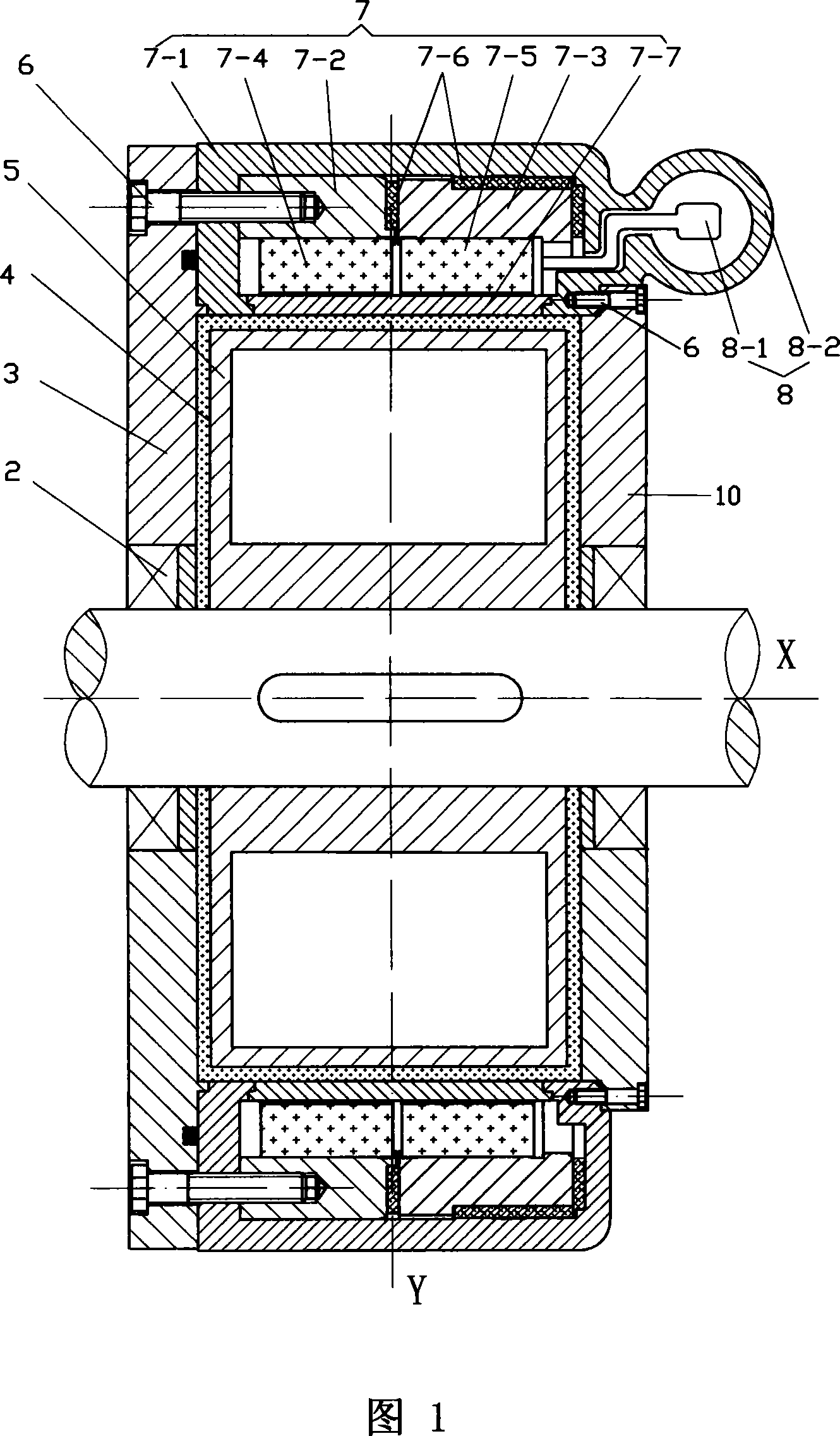
[0020] The embodiment shown in Figures 1 to 3 includes a rotor 5, a stator 7 on the outer circumference of the rotor 5, sealing covers 3, 10 covering both sides of the stator 7, and a fixed connection with the rotor 5 and fixed on the two sealing covers 3, 10 The drive shaft 1 supported by the upper bearing 2 has a closed cavity 4 between the rotor 5 and the surrounding stator part and the sealing covers on both sides, and the enclosed cavity 4 is filled with magnetorheological fluid. The stator 7 includes an annular hollow housing 7-1, an annular fixed holder 7-2 and an annular movable holder 7-3. The sealing covers 3 and 10 on both sides are fixed on both sides of the housing 7-1 by screws 6. The inner surface of the fixed cage 7-2 is fixed with permanent magnets 7-4 evenly distributed in the circumferential direction, the inner surface of the movable cage 7-3 is fixed with permanent magnets 7-5 evenly distributed in the circumferential direction, and the fixed cage 7- The arran...

Embodiment 2

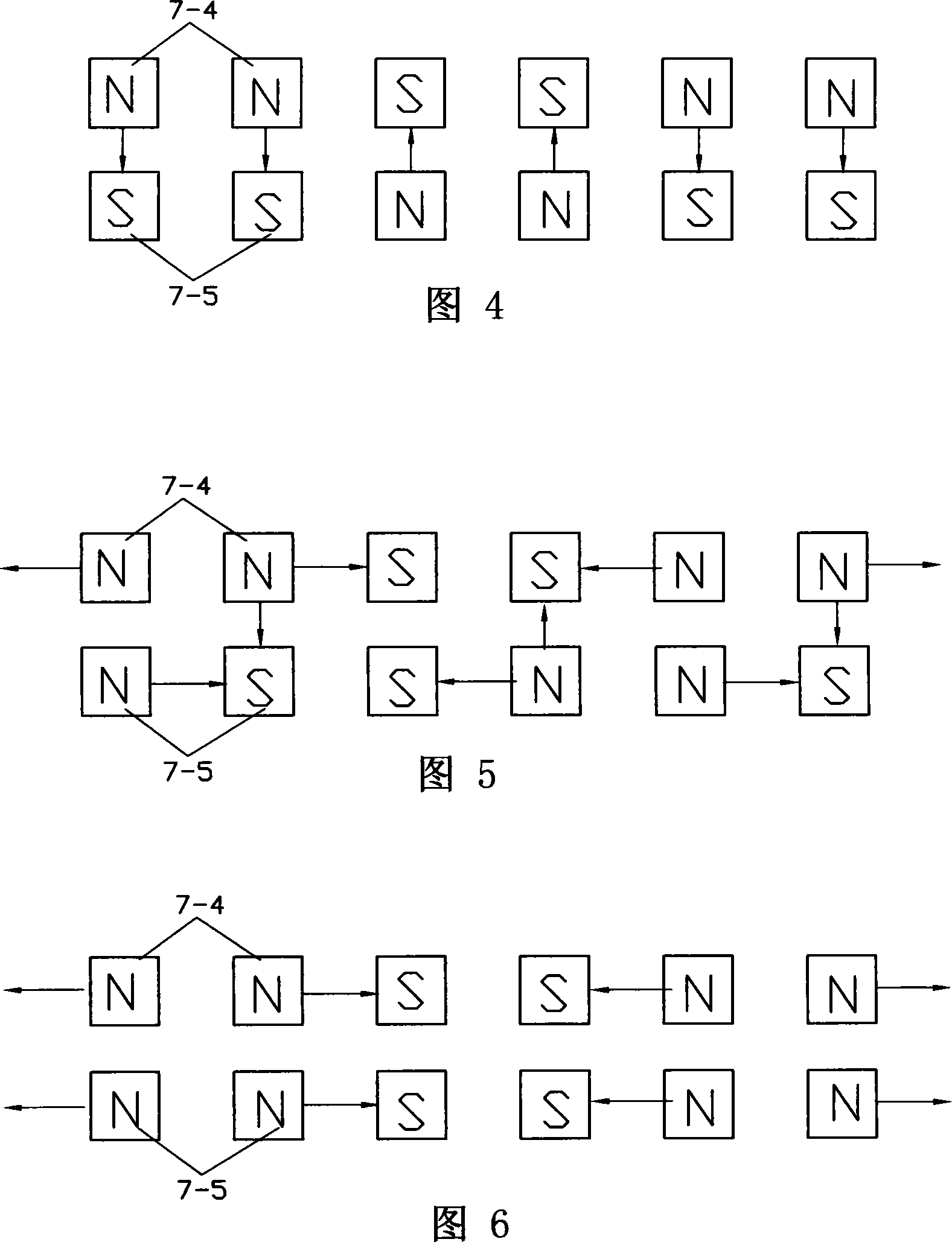
[0023] As shown in Figure 4, the polarity of the permanent magnets is set in the radial direction, that is, in the Y direction. Two permanent magnets in the same cage form a group, the polarity of the permanent magnets in the same group is the same, and the polarities of the permanent magnets of adjacent groups are different; Same as Example 1.

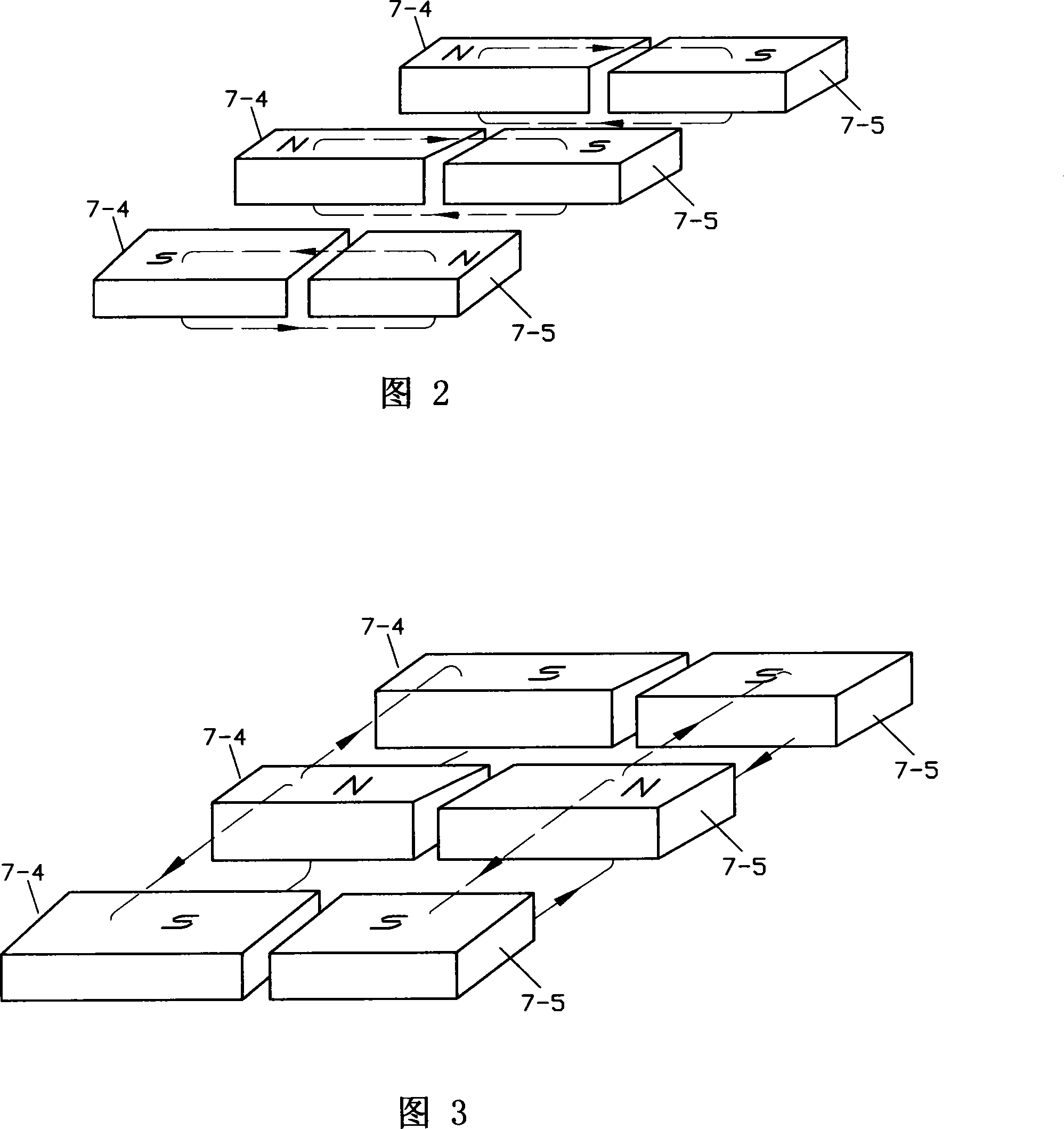
[0024] In this embodiment, when the permanent magnet group on the movable holder 7-3 and the permanent magnet group on the opposite fixed magnet holder 7-2 have different polarities, they belong to the axially adjacent permanent magnets on the two holders. The magnetic lines of force form a closed magnetic circuit. The direction of the closed magnetic circuit can be referred to the direction of the closed magnetic circuit in Figure 2. The magnetic lines of force do not pass through the magnetorheological fluid, and the brake is in a non-braking state.

[0025] When the movable cage 7-3 rotates one gear, the pitch between a permanent magne...


PUM


Abstract

The invention relates to a magneto-rheological fluid brake, comprising a rotor, a stator, a sealing cover, and a transmission shaft, which is characterized in that a plurality of closed cavities filled with magneto-rheological fluid are arranged around the rotor; the stator is composed of an annular hollow housing, an annular fixed retainer, and an annular movable retainer; a plurality of permanent magnets uniformly distributed in circumferential direction with the same regularity are fixed on the inner side surfaces of the fixed retainer and the movable retainer; the fixed retainer and the movable retainer with permanent magnets are axially paralleled in the casing; a plurality of windows are uniformly distributed on the inner side surface of the casing; two axially adjacent permanent magnets belonging to the fixed retainer and the movable retainer respectively share the same window; a magnetic-inductive plate is embedded in each window; the fixed retainer and the movable retainer are made of magnetic conducive materials, and the other parts of the casing are made of non-magnetic materials. The magneto-rheological fluid brake has the advantages of realization of brake, power saving, convenient operation and actualization, reliable brake performance by adopting permanent magnets as magnetic source, and changing direction of closed magnetic circuit through rotation of the movable retainer.

Description

Technical field [0001] The invention relates to a liquid resistance brake. Background technique [0002] The Chinese Patent Authorization Announcement No. 1231686C and the invention patent specification titled "Structurally Variable Rotary Magnetorheological Fluid Brake" discloses a brake, which includes a bearing end cover, a sealing cover, magnetic inner and outer cylinders, and electromagnetic Coil, rotating shaft, positioning key, bearing, magnetorheological fluid, turntable, sealing material. The magnetic inner and outer cylinders are cylinders made of magnetically conductive materials; the magnetic inner cylinder has a disc-shaped partition structure, and the rotating shaft passes through the magnetic inner cylinder to connect with the turntable; the electromagnetic coil is attached to the outer magnetic permeable cylinder. In the cylinder shell, it is put together on the magnetic inner cylinder; magnetorheological fluid is injected into the magnetic inner cylinder; the sea...

Claims


Application Information

Patent Timeline
Patent Type & Authority Applications(China)
IPC IPC(8): F16D57/00
Inventor 刘成晔
Owner JIANGSU UNIV OF TECH
Why Eureka
Try Eureka