Device and method for detecting defect of transparent material

A defect detection and light transmittance technology, applied in measurement devices, optical devices, optical testing of flaws/defects, etc., can solve problems such as decreased defect detection accuracy, weak light, residual noise components, etc.

Inactive Publication Date: 2008-07-23
FUJIFILM CORP
View PDF3 Cites 16 Cited by
  • Summary
  • Abstract
  • Description
  • Claims
  • Application Information

AI Technical Summary

Problems solved by technology

Therefore, light in the wavelength bands below 400nm and above 700nm remains as a noise component in the received light signal for defect determination, deteriorating the accuracy of defect detection
[0005] If the defect is small, the detected light will be weak

Method used


Image

  • Device and method for detecting defect of transparent material
  • Device and method for detecting defect of transparent material

Examples


Embodiment Construction

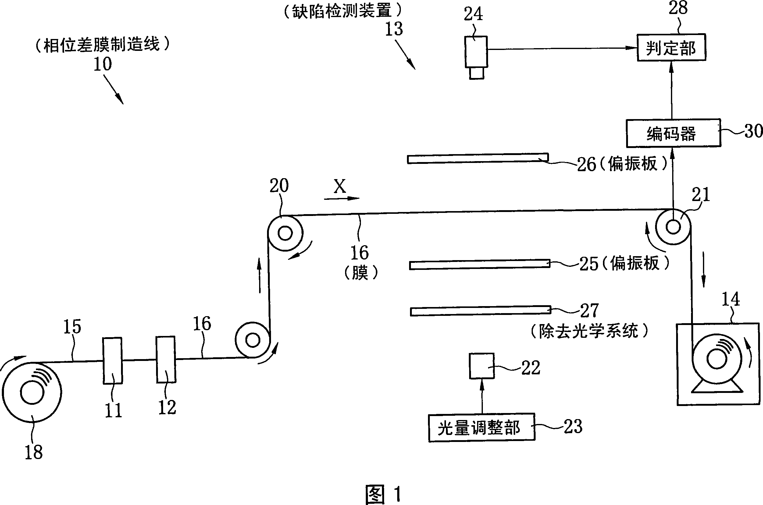
[0016] In FIG. 1 , a retardation film manufacturing line 10 includes an alignment film forming device 11 , a liquid crystal layer forming device 12 , a defect inspection device 13 , and a winding device 14 . The transparent resin film 15 and the retardation film 16 travel in the X direction in the figure by the winding by the winding device 14 .

[0017] The alignment film forming apparatus 11 applies a coating liquid containing a resin for forming an alignment film on the surface of the elongated transparent resin film 15 sent out from the film roll 18, and then heats and dries it. In this way, the resin layer for forming an alignment film is formed on the surface of the transparent resin film 15 . Then, the alignment film forming apparatus 11 performs a rubbing process on the resin layer for forming an alignment film of the transparent resin film 15 to form an alignment film.

[0018] The liquid crystal forming device 12 applies a coating liquid containing a liquid crystal ...


PUM


Abstract

The invention provides a flaw detecting device of transparent material. A first and second polarization plates are arranged above and below the film in orthogonal polarization mode. A projector irradiates light through the first polarization plate and a light receiving device receives light from the second polarization plate, therefore the flaw of the film is detected. A band filter is set between the first polarization plate and projector. The band filter removes the light of wave band below 420nm and above 700nm. There is no light of needless wave band into the light receiving device, thus the flaw detecting accuracy is increased.

Description

technical field [0001] The present invention relates to a defect detection device and a defect detection method for detecting defects of a light-transmitting material by using a polarizing plate. Background technique [0002] In order to improve the viewing angle of a liquid crystal display device, an optical compensation film (hereinafter, referred to as a retardation film) in which a liquid crystal layer having optical anisotropy is formed on a transparent film can be used. The retardation film is produced by forming an alignment film on a long transparent film, and forming a liquid crystal layer by coating and drying a liquid crystal on the alignment film (for example, refer to JP-A-9-73081). Although these manufacturing steps are carried out under strict control, it is still difficult to completely eliminate defects such as uneven molecular orientation due to contamination and adhesion of foreign substances, uneven thickness of the transparent film constituting the suppo...

Claims


Application Information

Patent Timeline
Patent Type & Authority Applications(China)
IPC IPC(8): G01N21/958G02F1/13
CPCG01B11/30G01N21/88G01N21/892G02B5/30
Inventor 中岛健胁田武高桥一平樋口学
Owner FUJIFILM CORP
Why Eureka
Try Eureka