Shunt release with indicated function

A shunt release with indication technology, applied in the direction of switchgear status indication, protection switch operation/release mechanism, etc., can solve the problem of inability to distinguish whether it is in normal working state or disconnected state, difficult to operate wiring, and complicated wiring and other problems to achieve the effect of saving assembly time, avoiding failures and simple assembly process

Inactive Publication Date: 2008-07-23
LEGRAND LOW VOLTAGE ELECTRICAL APPLIANCES WUXI
View PDF0 Cites 12 Cited by
  • Summary
  • Abstract
  • Description
  • Claims
  • Application Information

AI Technical Summary

Problems solved by technology

[0003] The shunt release matched with the current miniature circuit breaker generally has two structural forms: a, two-terminal structural form, this structural form does not have an indicating function, and it cannot be judged whether it is in a normal working state or a disconnected state; b. 1. Four terminal structure, this structure has indicat

Method used


Image

  • Shunt release with indicated function
  • Shunt release with indicated function
  • Shunt release with indicated function

Examples


Embodiment Construction

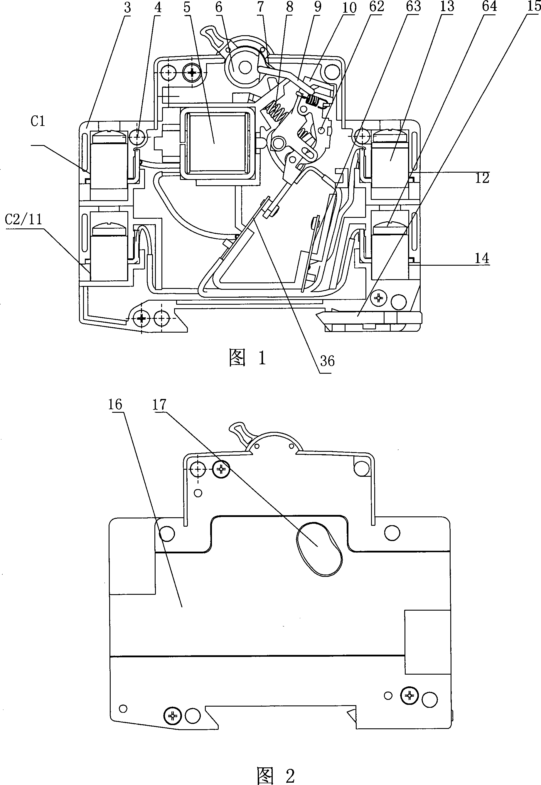
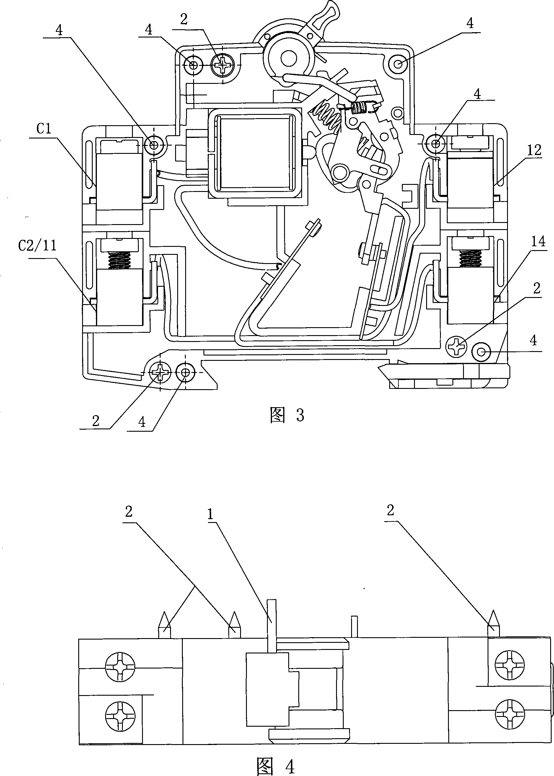
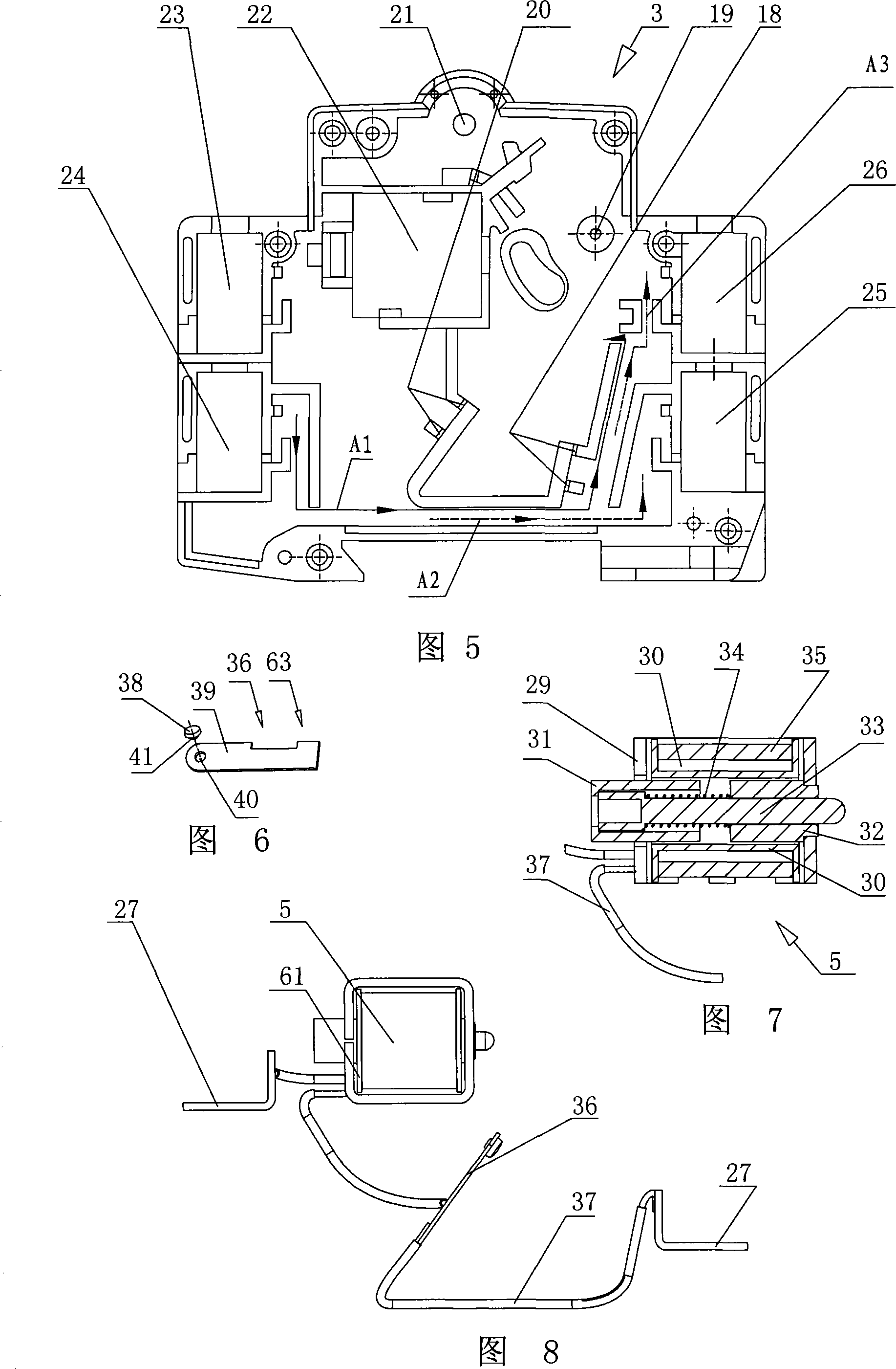
[0028] The part numbers in the figure indicate: 1, 62, 44, 51 are metal shafts, 2 is assembly screws, 3 is base, 4 is rivets, 5 is electromagnetic system, 6 is handle, 7 is handle spring, 8 is mechanism Spring, 9 is the connecting rod, 10 is the tripping device, 63 is the right contact, 13 is the rail type terminal, 64 is the terminal screw, 15 is the clip, 16 is the cover, 17 is the sealing insulation board, 18, 20 19 is a card slot, 19 is a hole, 21 is a shaft, 22 is a fixing slot, 23, 24, 25, 26 are terminal slots, 27 is a wiring seat, 29 is a yoke, 30 is a coil frame, 31, 32 are left and right Iron core, 33 is the push rod, 34 is the spring, 35 is the coil winding, 36 is the left contact, 37 is the wire, 38 is the static contact, 60 is the moving contact, 39 is the contact plate, 40 is the riveting hole, 41 is the contact shaft, 43 is the jumper, 45, 58 are two holes of the jumper part, 46 is the jumper part, 47 is the changeover contact, 48 is the changeover contact part,...


PUM


Abstract

The invention is adapted to match with small-size circuit breakers, in particular to a shunt trip with an indicating function. According to the technical scheme provided by the invention, a base is provided with a cover, and a main shaft, a trip gear and an electromagnetic system are arranged inside the base. And the main shaft is arranged inside a hole on the upper right side of the base, and the trip gear can be rotatablely arranged on the main shaft. The electromagnetic system is disposed inside a retaining groove which is arranged on the upper left side of the base. The left and right sides of the base are respectively provided with a wire connecting terminal. The invention is characterized in that a wire connecting terminal C2/11 is connected to phase lines or a positive electrode of the power, a wire connecting terminal C1 is connected to an N line or a negative electrode of the power by employing a normally open push button, an indirect indicating lamb L1 is connected between a wire connecting terminal 12 and the N line or the negative electrode of the power, and an indirect indicating lamb L2 is connected between a wire connecting terminal 14 and the N line or the negative electrode of the power. The trip has the indicating function, which is capable of being judged whether the trip is in normal working, or at off-state when using the trip.

Description

technical field [0001] The invention is suitable for matching a small circuit breaker, specifically a shunt tripper with indicating function. Background technique [0002] Miniature circuit breakers used in the field of fire protection need to be matched with shunt releases. The purpose is to forcefully break the circuit at a long distance when the load controlled by the miniature circuit breaker has a fire or other fault, so as to reduce unnecessary economic losses. [0003] The shunt release matched with the current miniature circuit breaker generally has two structural forms: a, two-terminal structural form, this structural form does not have an indicating function, and it cannot be judged whether it is in a normal working state or a disconnected state; b. 1. Four terminal structure, this structure has indication function, but the internal wiring is more complicated, it is easy to break during the assembly process and long-term movement process and cause actual effect, an...

Claims


Application Information

Patent Timeline
IPC IPC(8): H01H71/04H01H71/24
Inventor 晏国云韩瑄王振宇
Owner LEGRAND LOW VOLTAGE ELECTRICAL APPLIANCES WUXI
Why Eureka
Try Eureka