Check patentability & draft patents in minutes with Patsnap Eureka AI!

4-level logic decoder

A decoder and level technology, applied in the field of multi-level logic, can solve problems such as complex design, timing verification, and hindering modeling

Inactive Publication Date: 2008-07-23
NXP BV
View PDF0 Cites 4 Cited by
  • Summary
  • Abstract
  • Description
  • Claims
  • Application Information

AI Technical Summary

Problems solved by technology

Current 4-level logic decoders use delay cells to detect differences between dynamic and static signals, and use flip-flops to store these differences and iterate over the 2-bit data sequentially, so this complicates the design
In addition, the use of delay cells prevents the use of hardware design language (HDL) to model the decoding circuit, which requires manual gate level implementation and manual timing verification

Method used


Image

  • 4-level logic decoder
  • 4-level logic decoder
  • 4-level logic decoder

Examples


Embodiment Construction

[0013] The invention can be modified through various modifications and alternative forms, some specific examples of which will be shown and described in detail by way of example shown in the drawings. It should be understood, however, that the intention is not to limit the invention to the particular embodiments described. On the contrary, the invention covers all modifications, equivalents, and alternatives falling within the spirit and scope of the invention as defined by the appended claims.

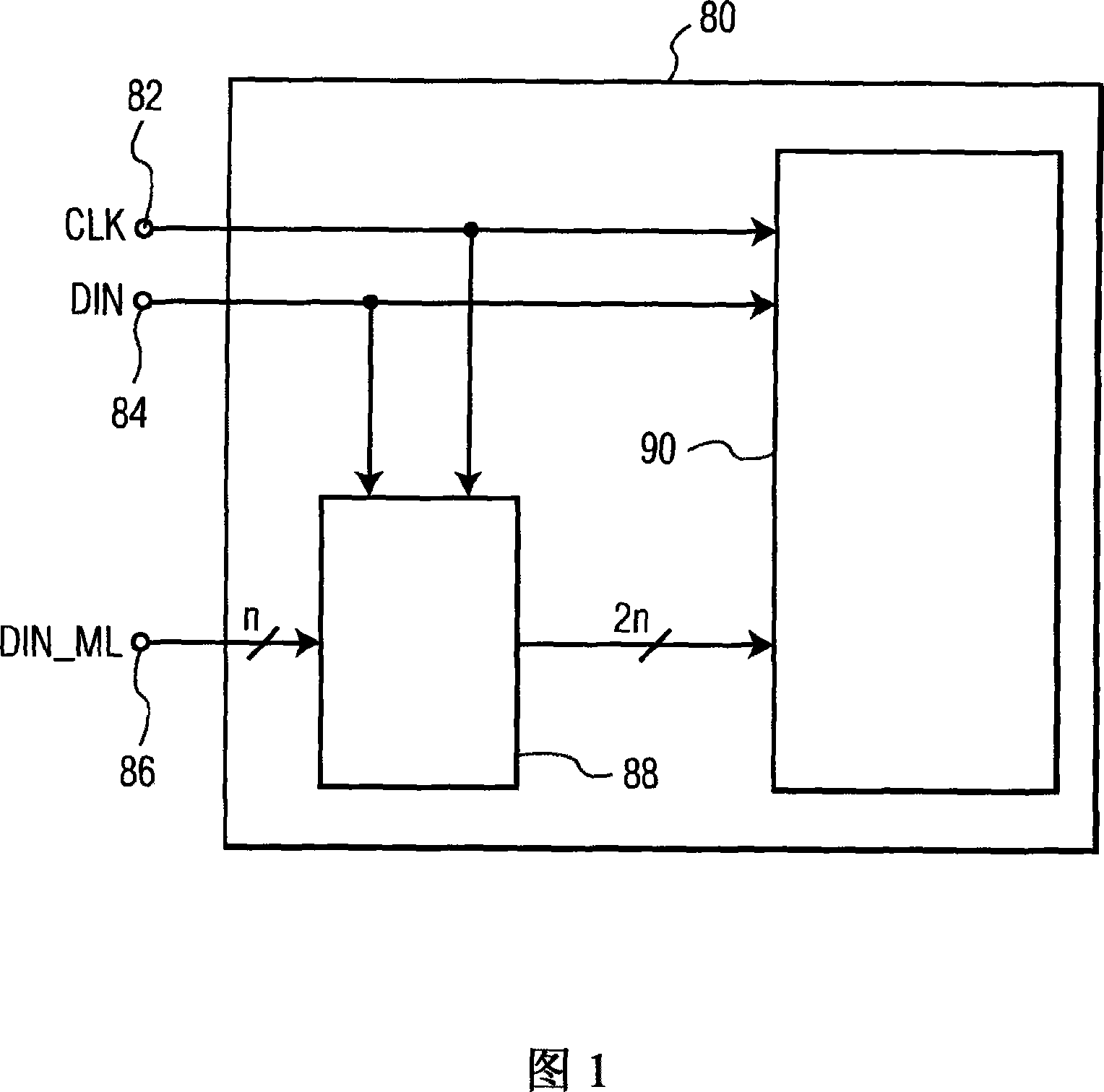
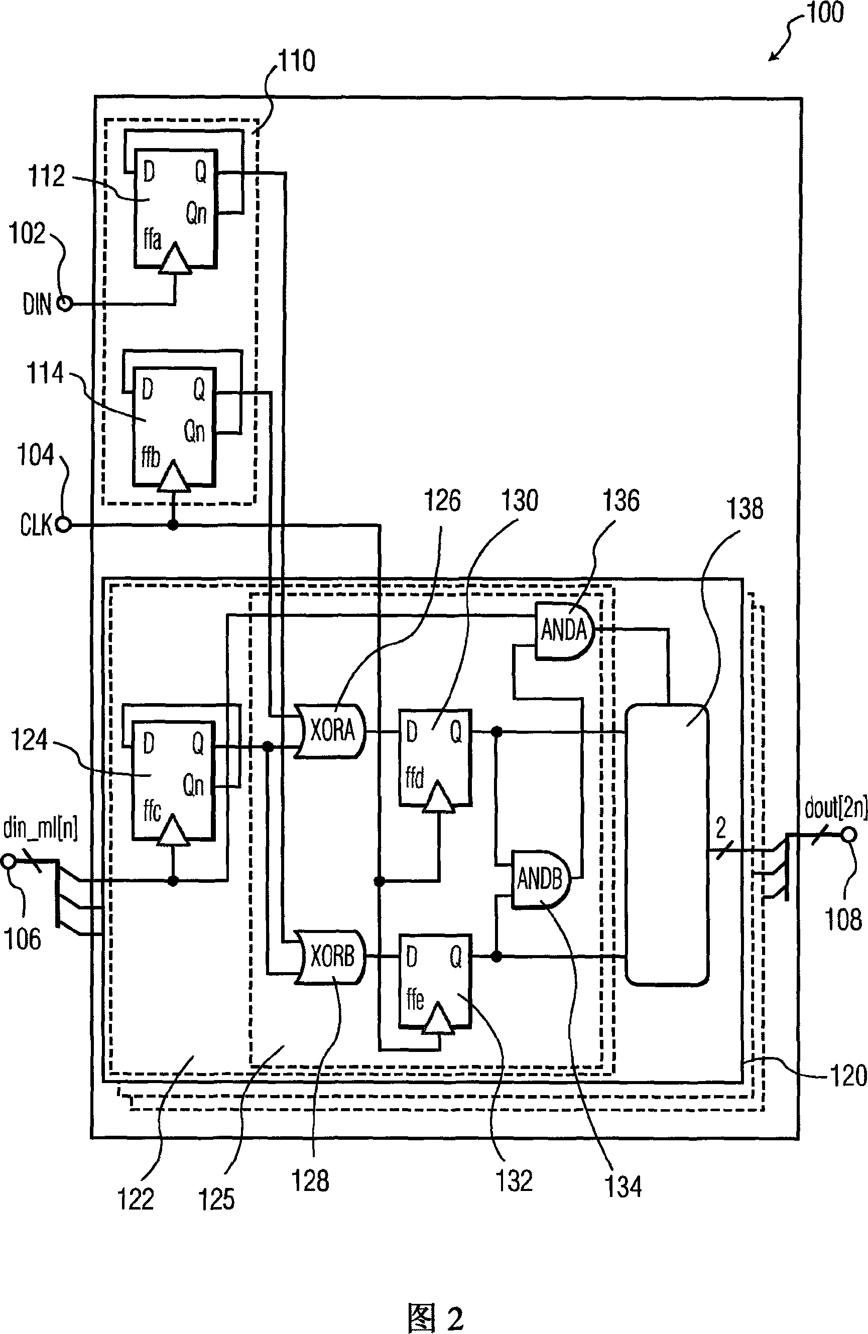
[0014] Traditional digital circuits only use high or low levels to represent the binary value '1' or '0' in the data bit. In this case, n bits can be used to represent a 2n-bit number. In multi-level logic, the number of levels used for data transmission in a single data channel is p, and p>2. For example, in a circuit powered by a 4V power supply, p=4, and levels 4V, 3V, 2V, and 1V are used for single-channel data transmission. This enables an n-channel data bus to represent 4n bit...


PUM


Abstract

The present invention relates to a 4-level logic decoder for decoding n 4-level input data signals into n 2-bit signals. The 4-level logic decoder comprises n decoding circuits (120) with each decoding circuit comprising comparison circuitries (125) for comparing the 4-level input data signal with a clock signal and a one-bit data signal. In dependence upon the comparison results signals are provided to a decode logic circuit (138), which are indicative of a data bit value of the 4-level input data signal representing one of the clock signal, the one-bit data signal, and static values of the 4-level input data signal. In dependence upon the signals the decode logic circuit (138) generates then a 2-bit output data signal. The 4-level logic decoder is easily implemented using simple circuit of logic components, which allow modeling using an HDL.

Description

[0001] This application claims application S / N: 60 / 702,052 (Attorney Docket No. 002087US1) entitled "An Efficient Implementation of a 4-Level. N-Wire to 2N-Bit Logic Decoder," filed July 22, 2005 priority, and this document is incorporated herein by reference in its entirety. technical field [0002] The present invention relates generally to multilevel logic, and more particularly to a circuit for decoding n 2-bit data from a 4-level logic data path used in conjunction with a high-speed serial bus. Background technique [0003] High-speed serial buses are used in a variety of applications, including computer systems, computer networks, and telecommunications systems. The goal is to transfer as much data as possible, as quickly as possible, and as accurately as possible. Traditional digital circuits use only two levels, high or low - corresponding to the binary value '1' or '0' in a data bit. An alternative to traditional digital circuits is to use multi-level encoded data...

Claims


Application Information

Patent Timeline
Patent Type & Authority Applications(China)
IPC IPC(8): H03M5/20H03K19/094
CPCH03M7/06
Inventor 罗伯特·赫勒伊
Owner NXP BV
Features
  • R&D
  • Intellectual Property
  • Life Sciences
  • Materials
  • Tech Scout
  • Unparalleled Data Quality
  • Higher Quality Content
  • 60% Fewer Hallucinations
Learn More