Multistage jounce bumper

一种缓冲器、颠簸力的技术,应用在汽车悬架系统领域,能够解决不舒服等问题,达到改善感觉与控制性的效果

Active Publication Date: 2008-07-30
GM GLOBAL TECH OPERATIONS LLC
View PDF1 Cites 15 Cited by
  • Summary
  • Abstract
  • Description
  • Claims
  • Application Information

AI Technical Summary

Problems solved by technology

This sudden jerk force and transfer of energy to the frame essentially manifests itself as a strong jolt in the passenger compartment which can create load management issues in addition to rough ride discomfort

Method used


Image

  • Multistage jounce bumper
  • Multistage jounce bumper
  • Multistage jounce bumper

Examples


Embodiment Construction

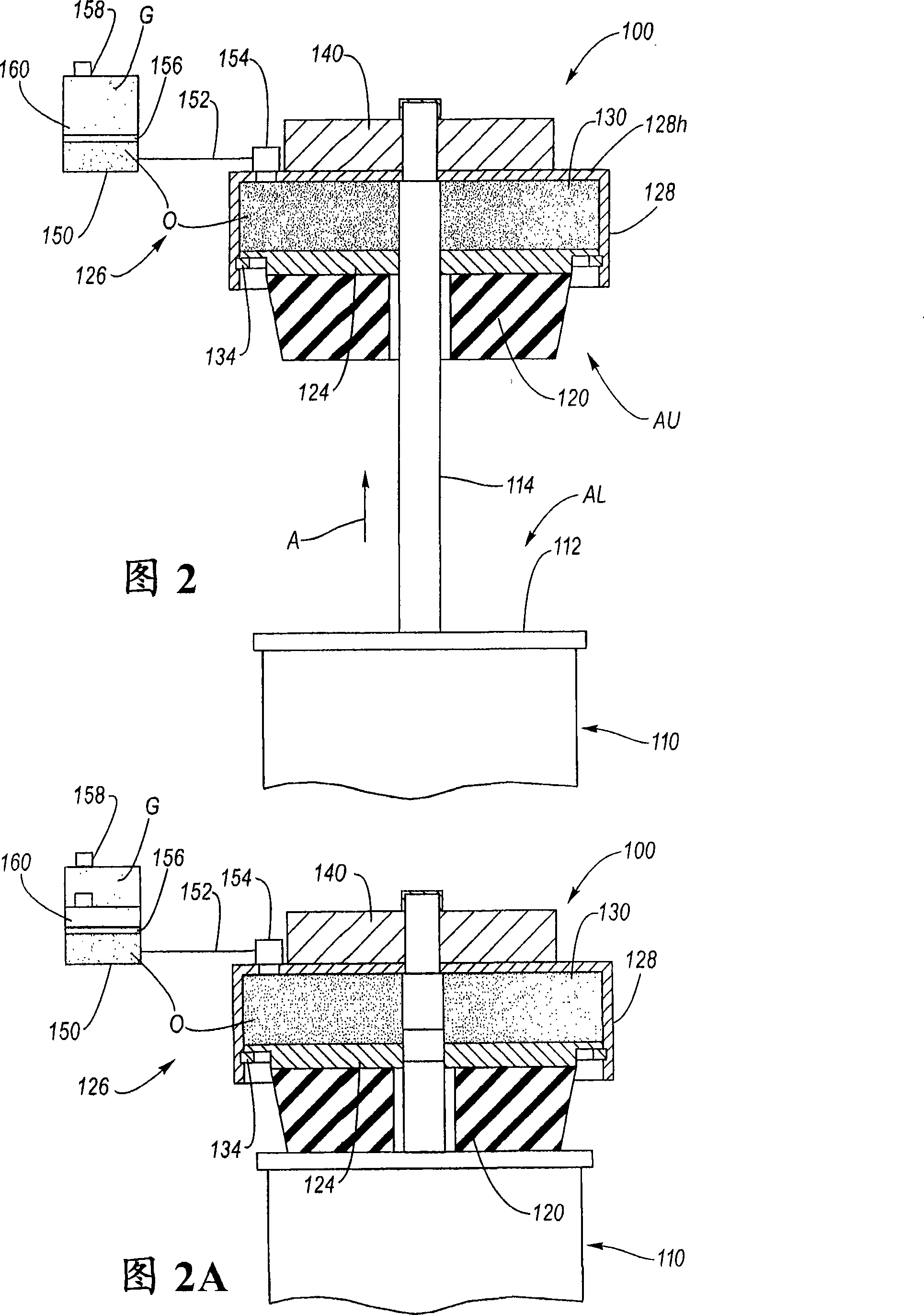
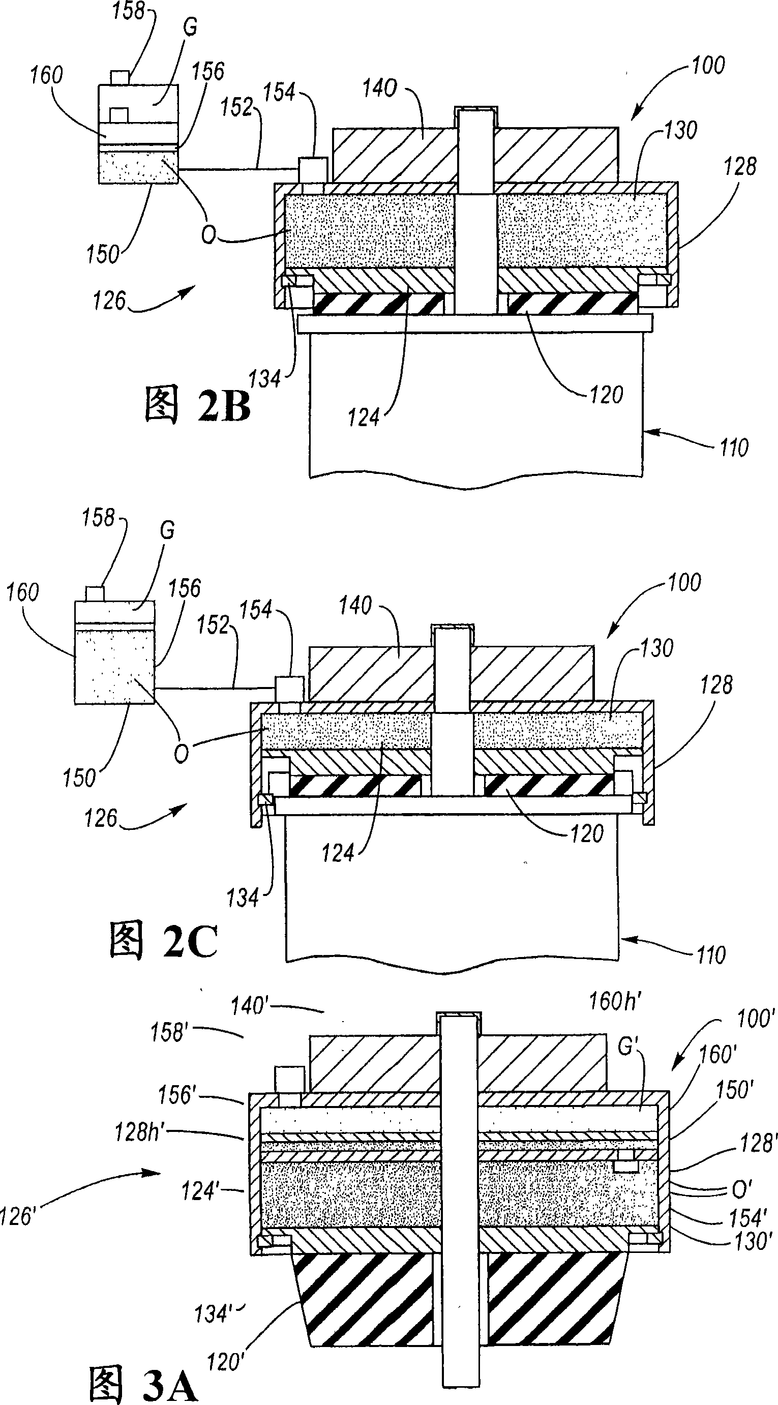
[0024] Referring now to the drawings, FIGS. 2 through 6 illustrate various aspects of the structure and function of a multi-stage jounce bumper in accordance with the present invention. The multi-stage jounce bumper is a novel synthesis of a jounce bumper pad, an adjustable hydraulic jounce bumper, and related damper components. The resulting extended bump management provides improved ride feel and enhanced load control capacity for high energy, uneven terrain inputs. While any type of damper may be used with the present invention (see discussion of dampers above), the most preferred form of damper is a strut.

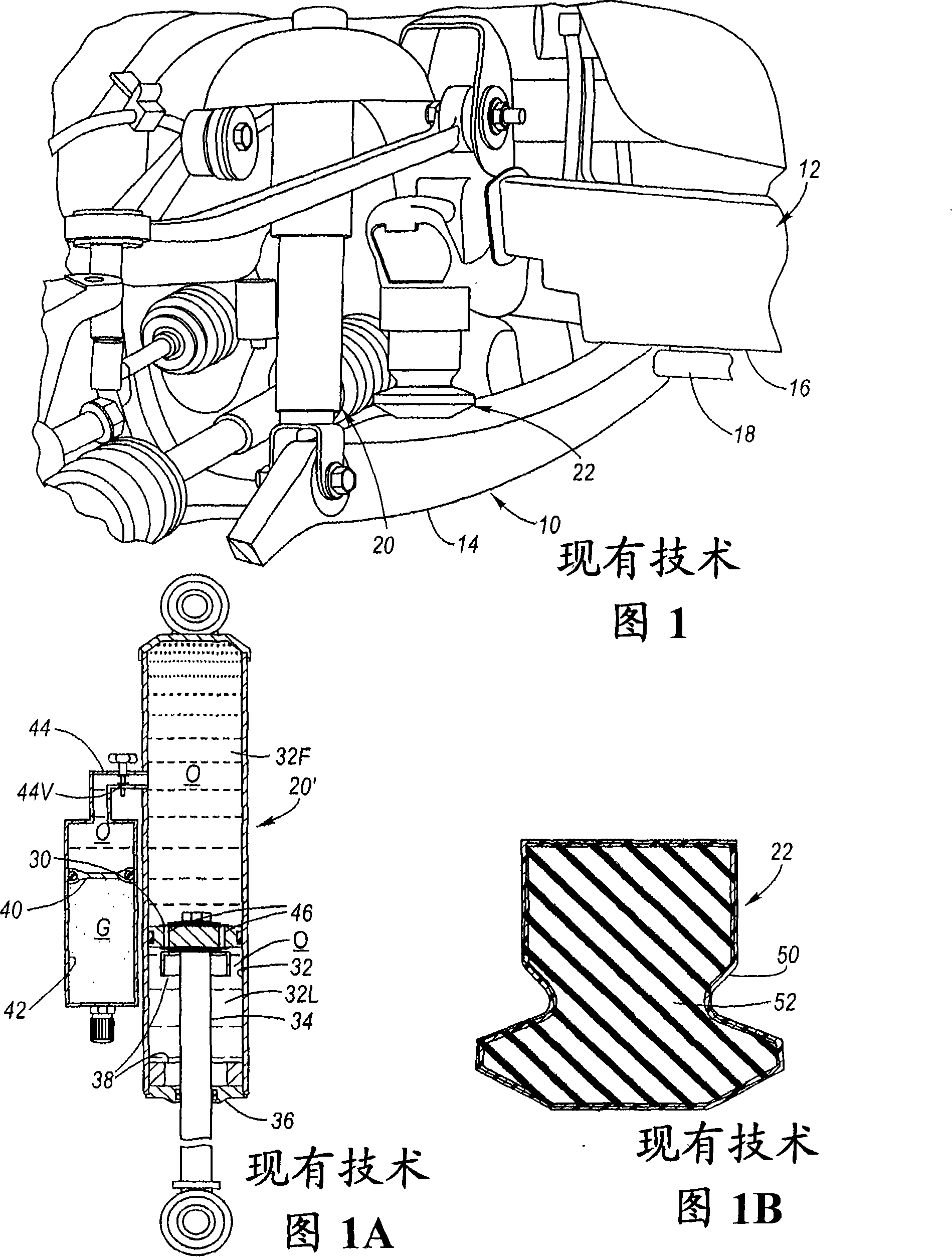
[0025] Referring first to FIG. 2 , there is shown a multi-stage jounce bumper 100 in accordance with the present invention. The lower aspect AL of the multi-stage jounce bumper 100 includes a damper 110 (i.e., a strut or shock absorber) connected to a joint or control arm of a suspension system generally relative to that of FIG. A shock absorber 20 is shown wherein t...


PUM


Abstract

A multi-stage jounce bumper comprising a jounce pad integrally formed with a hydraulic jounce bumper wherein the shock absorbing properties of the hydraulic jounce bumper are provided while providing the shock / spring properties of the jounce pad. The hydraulic response of the hydraulic jounce bumper can be adjusted by adjusting the hydraulic flow relative to the channeled hydraulic fluid reservoir. When the maximum pitch is approaching, jounce force and energy are exchanged with the jounce bumper pad in the first stage, and then with the hydraulic jounce bumper in the second stage at a predetermined amount of compression. Thereafter, mechanical adjacency is provided as a third level of jerk management.

Description

technical field [0001] This invention relates to automotive suspension systems, and more particularly to bumper mounts, jounce bumpers, and conventional shock absorbers. More specifically, the present invention relates to a multi-stage jounce bumper, which is the combination of a jounce pad and a hydraulic jounce bumper, the combination providing enhanced energy absorption characteristics of the suspension system as well as improved ride characteristics. Background technique [0002] Motor vehicle suspension systems are configured such that the wheels follow changes in elevation of the road surface as the vehicle travels along the road surface. When encountering a rise in the road surface, the suspension system responds with a "bump," in which the wheels are able to move upward relative to the vehicle's frame. On the other hand, when encountering a dip in the road surface, the suspension responds with "kickback," in which the wheels are able to move downward relative to the...

Claims


Application Information

Patent Timeline
Patent Type & Authority Applications(China)
IPC IPC(8): B60G13/16B60G17/056
CPCB60G17/06B60G17/08B60G2202/24B60G2204/129F16F9/58F16F13/06
Inventor S·G·奎因G·J·法德勒W·C·格雷戈里
Owner GM GLOBAL TECH OPERATIONS LLC
Why Eureka
Try Eureka