Soil stripping device

A technology for stripping equipment and soil, which is applied in earth movers/shovels, excavators, mechanically driven excavators/dredgers, etc., and can solve complex brake equipment and other problems

Inactive Publication Date: 2008-07-30
BAUER MASCH GMBH
View PDF3 Cites 12 Cited by
  • Summary
  • Abstract
  • Description
  • Claims
  • Application Information

AI Technical Summary

Problems solved by technology

For the safety of the rotation of the work unit separated f

Method used


Image

  • Soil stripping device
  • Soil stripping device
  • Soil stripping device

Examples


Embodiment Construction

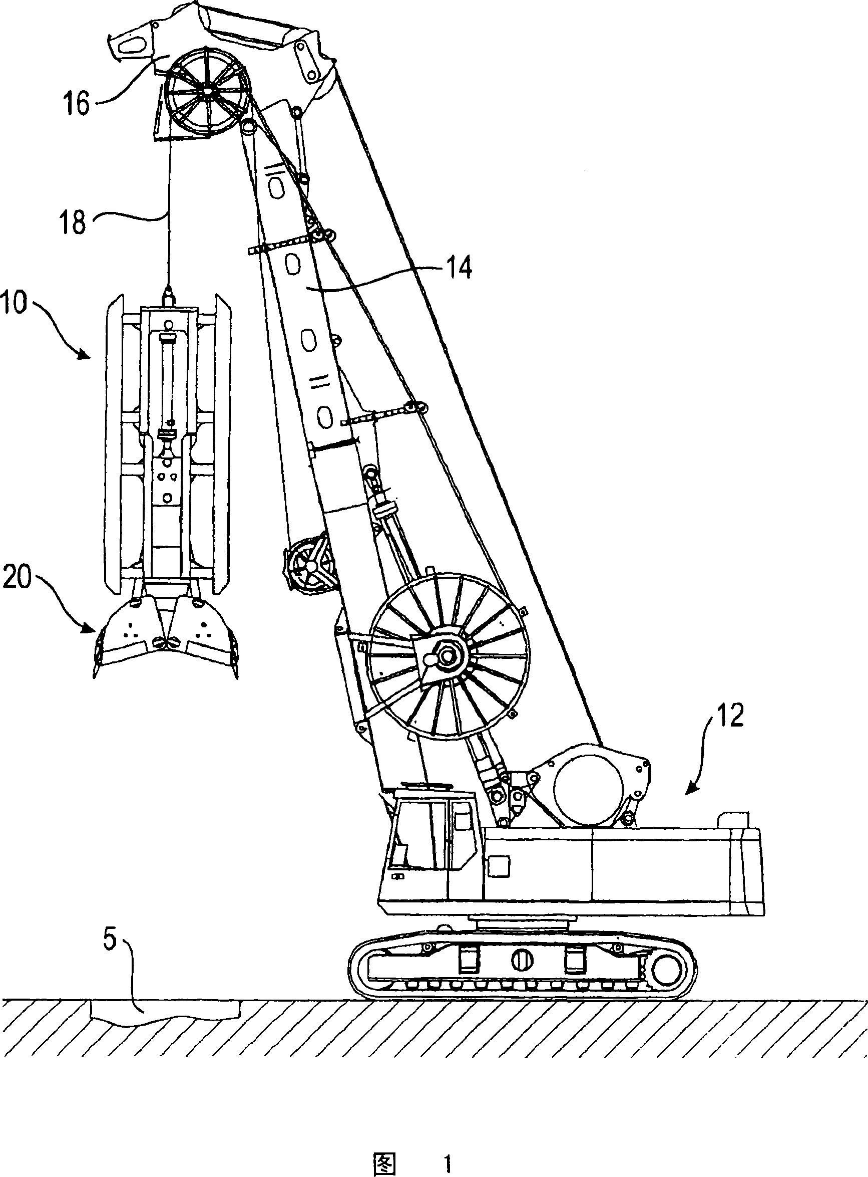
[0028] The basic construction of a soil stripping device 10 according to the invention for forming a trench 5 in soil is schematically shown in FIG. 1 . A working unit 20 for excavating a trench 5 is arranged vertically displaceable on a carrier 12 by means of a lifting device 18 consisting of several support cables, wherein the carrier has a mast head 16 The approximately vertically oriented mast 14 .

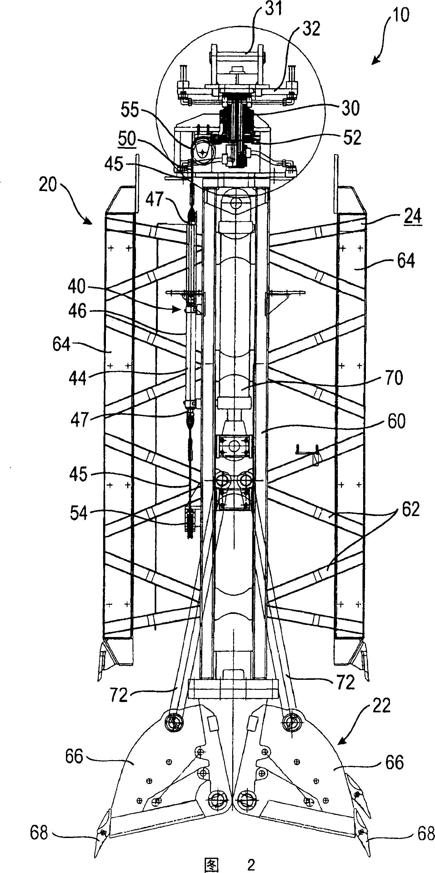
[0029] According to FIG. 2 , a soil stripping device 10 according to the invention is shown designed as a ditch wall grab. The ditch wall grab comprises a frame 24 with a centrally arranged longitudinal girder 60 , on which lateral guide plates 64 are arranged in a known manner via crossbars 62 . Two grappling blades 66 with teeth 68 pivot at the lower end of the longitudinal spar 60 to act as the soil stripping tools 22 . By means of a hydraulically actuated cylinder 70 centrally located on the longitudinal spar 60, the grab blade 66 can be opened or closed by means of an a...


PUM


Abstract

The invention relates to a soil stripping device, in particular to a ditch wall grab, which includes: a base body that can be connected with a carrying tool; a soil operation tool is arranged on it and is rotatably supported on the base body by means of a bearing device a working unit; and a rotation device for rotating the working unit with respect to the base body. The rotary device has at least one linear drive and a cable or chain drive, by means of which the linear motion produced by the linear drive can be converted into a rotary motion.

Description

technical field [0001] The present invention relates to a soil stripping device, in particular to a ditch wall grab, which includes a base that can be connected with a carrying tool, on which a soil operating tool is rotatably supported on the ground by means of a bearing device A working unit on the base, and a rotating device for rotating the working unit with respect to the base around a rotational axis. Background technique [0002] This equipment is used to excavate pits or trenches in the soil that are primarily used to form foundations or seals in the soil. When using grapples with grapples, especially when relatively deep trench walls are formed, there is the risk that asymmetry, in particular due to the asymmetric distribution of the teeth on the grapple, will lead to uncontrolled A welcome deviation from the vertical. To compensate for this, it is known to turn the grapple 180 degrees at regular intervals, especially after each stroke. By doing so, deviations ca...

Claims


Application Information

Patent Timeline
IPC IPC(8): E02F3/47E02F9/20E02F5/02
CPCE02D17/13E02F3/413E02F3/475E02F5/02E02F5/00
Inventor S·F·洛费尔霍尔茨J·迈耶霍弗
Owner BAUER MASCH GMBH
Why Eureka
Try Eureka