Copper wire tin-plating drier

A copper wire tin-plating and drying technology, applied in progressive dryers, dryers, drying solid materials, etc., can solve the problems of copper wire quality decline, long time, poor drying effect, etc., to speed up work efficiency , the effect of high work efficiency

Inactive Publication Date: 2008-07-30
LINOYA ELECTRONIC TECHNOLOGY CO LTD
View PDF0 Cites 8 Cited by
  • Summary
  • Abstract
  • Description
  • Claims
  • Application Information

AI Technical Summary

Problems solved by technology

[0002] In the prior art, copper wires are usually dried naturally after tinning, and a longer distance is set between the feed wheel and the discharge wheel, allowing the tinned copper wires to dry naturally in this distance, so that The setting time is long and the efficiency is low; there is also a fan added to this distance to speed up the drying speed of tin on the copper wire, but the wind blown by the fan is scattered, and the drying effect is not good, resulting in a decline in the quality of the copper wire

Method used


Image

  • Copper wire tin-plating drier
  • Copper wire tin-plating drier
  • Copper wire tin-plating drier

Examples


Embodiment Construction

[0015] Below in conjunction with accompanying drawing, specific embodiment is described:

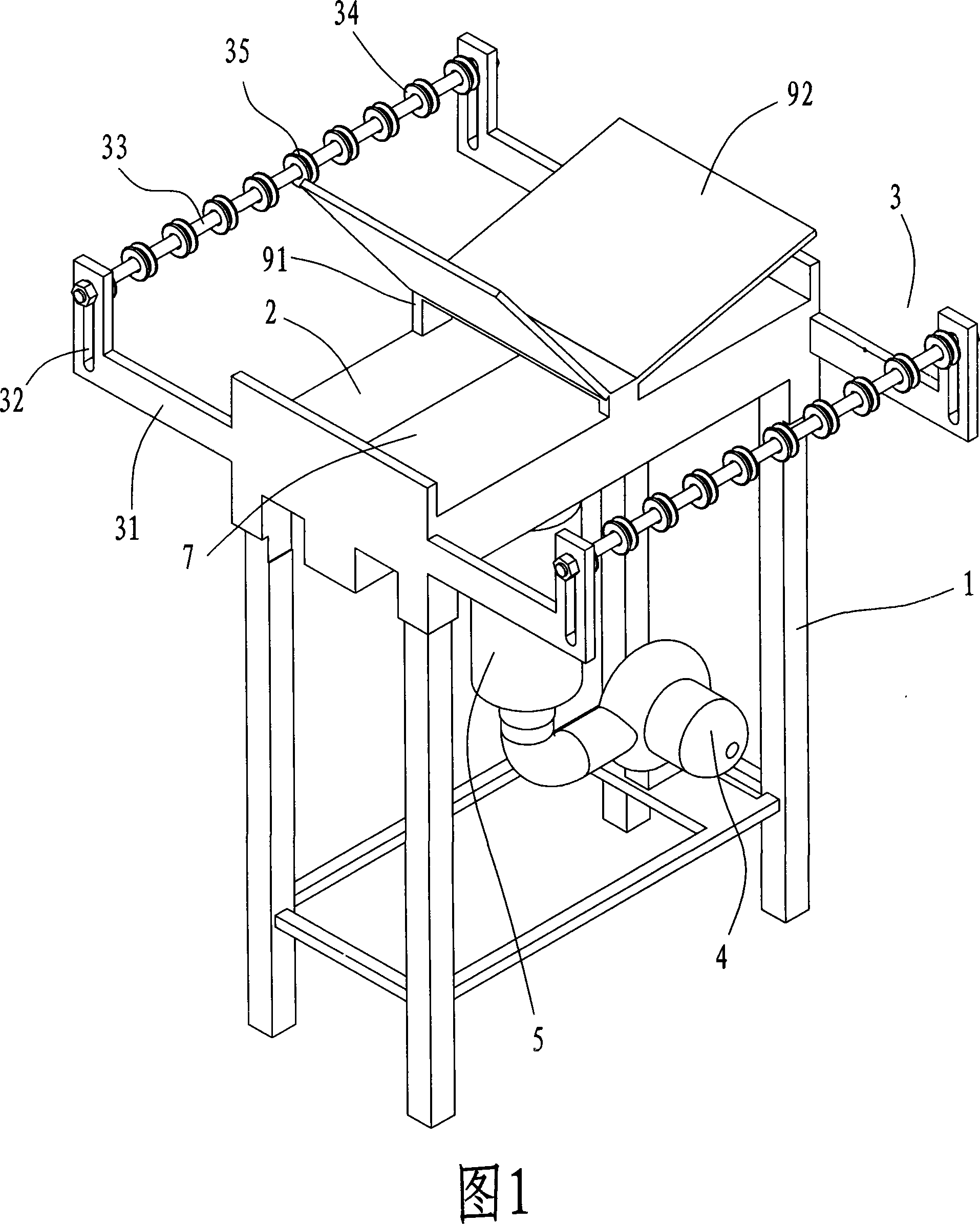
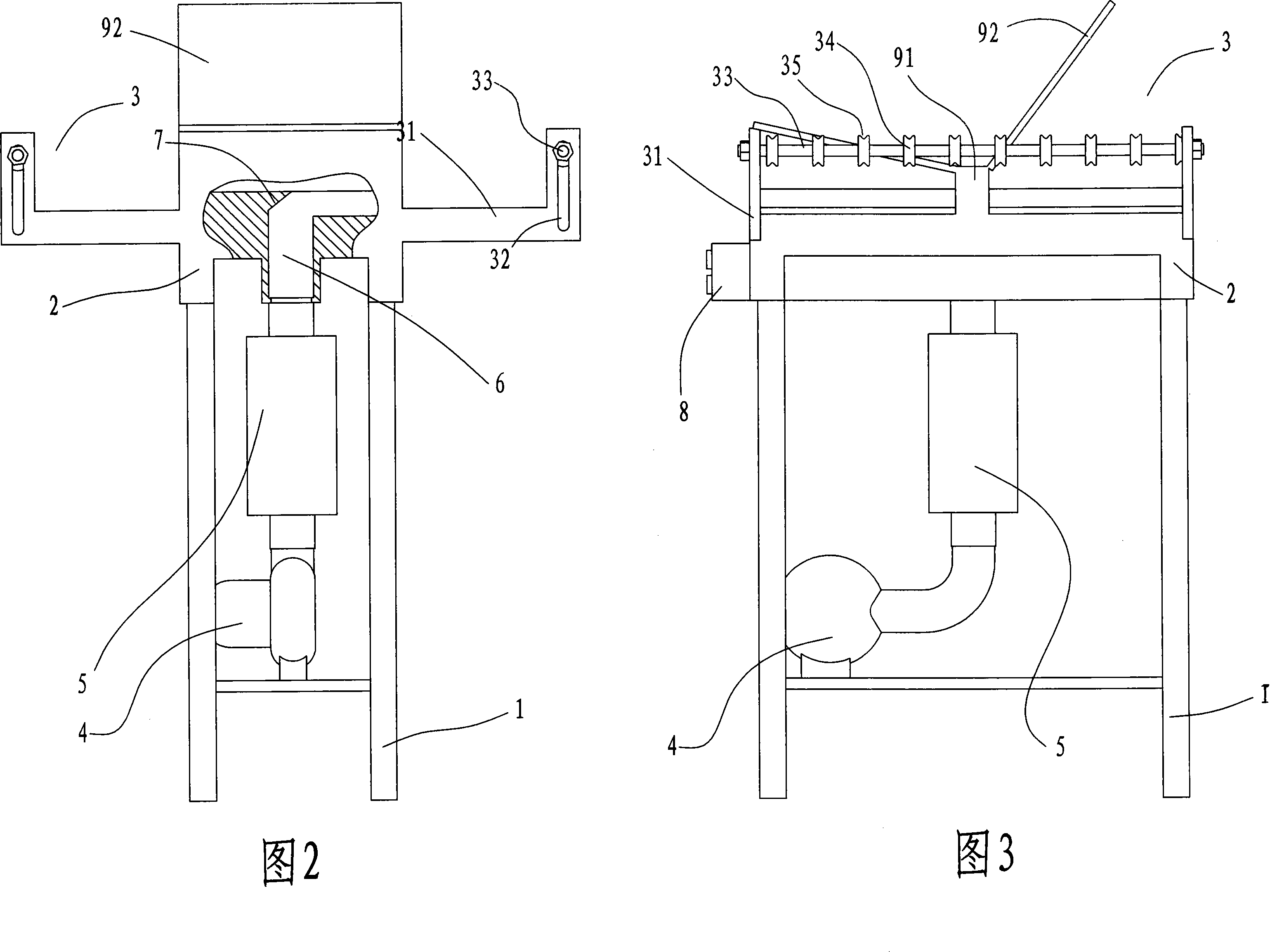
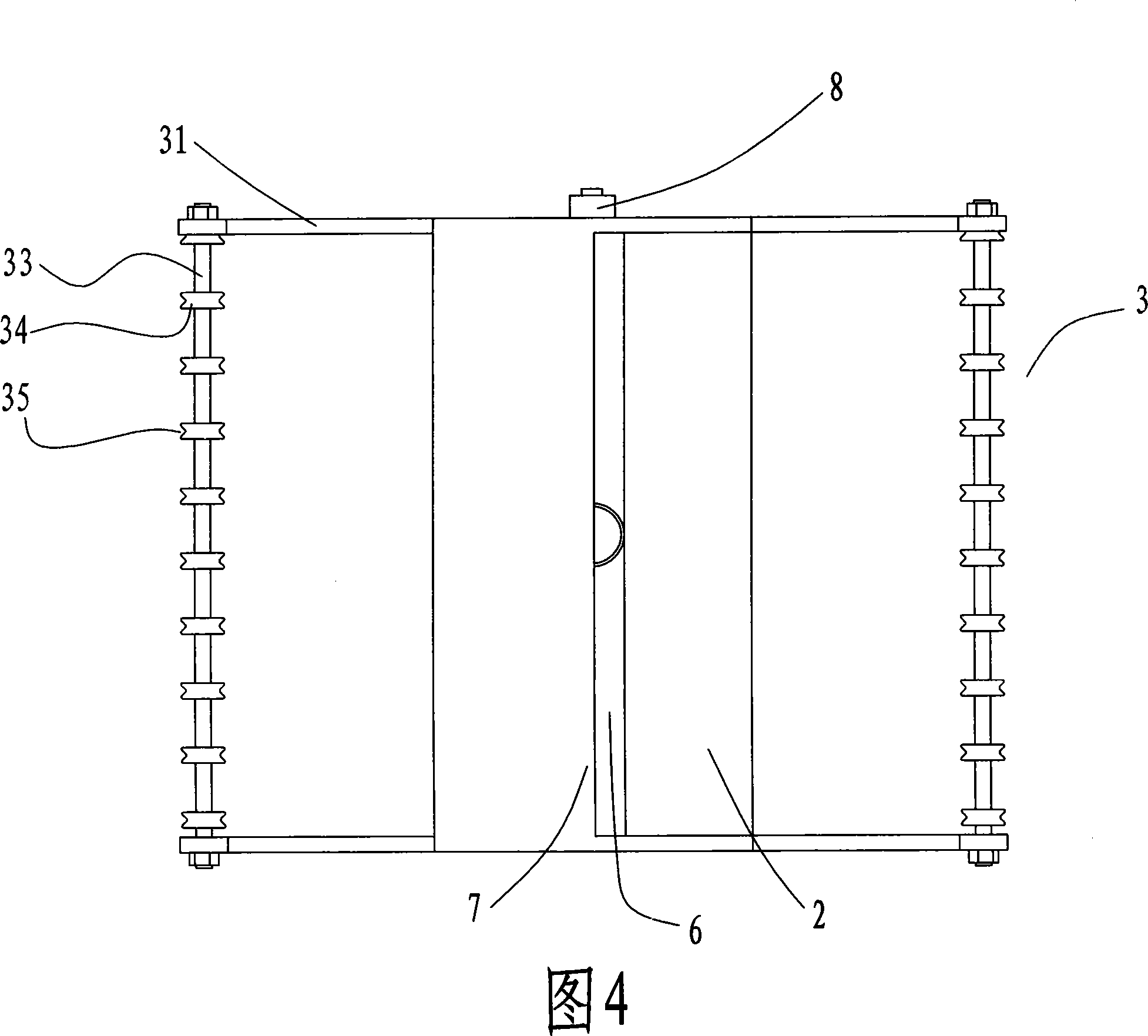
[0016] As shown in Fig. 1, Fig. 2, Fig. 3, and Fig. 4, a copper wire tinning dryer includes a frame 1, a workbench 2 is arranged on the upper plane of the frame 1, and a workbench 2 is arranged on the outer wall of both sides of the workbench 2. Wire outlet device 3; the wire inlet and outlet device 3 includes two upwardly extending L-shaped struts 31 protruding from both ends of the opposite side walls of the workbench 2, and the short struts of the L-shaped struts 31 are There is a long hole 32 in the longitudinal direction, and a wheel shaft 33 is threaded between the two long holes 32, and several rotating wheels 35 are sleeved at intervals on the wheel shaft 33, and an annular groove 35 is provided on the rotating wheel 34; the middle part of the workbench 2 A downwardly sunken air distribution groove 6 is provided, and the bottom of the air distribution groove 6 is provided with an...


PUM


Abstract

The invention discloses a copper line tinning dryer which comprises a frame work, wherein, a worktable which is arranged horizontally is fixedly connected with the plane of the frame work, a wire ingoing and outgoing device is arranged on the outer walls on both sides of the worktable, and a concave wind distributing groove is arranged in the middle of the worktable. A wind inlet is arranged in the bottom of the wind distributing groove and is connected with a heat generation device by a pipeline, and the heat generation device is connected with an air blower by a pipeline, wherein, the air blower is fixed on the frame work. By adopting the air blower and the wind distributing groove, centralized blowing can be ensured and the work efficiency is accelerated. A wind guide board is added on one side of a wind outlet of the wind distributing groove, the blowing is enabled to be more centralized, and the work efficiency is higher. Because a heating device is added, wind which is blown out has high temperature, and quality of the copper line which is dried can be ensured while the work efficiency is accelerated. A wind stopping machine cover is arranged above the wind distributing groove, so the work space with an air whirlpool is formed over the worktable, thus, the work efficiency is accelerated.

Description

technical field [0001] The invention relates to drying equipment, in particular to a copper wire tinning dryer. Background technique [0002] In the prior art, copper wires are usually dried naturally after tinning, and a longer distance is set between the feed wheel and the discharge wheel, allowing the tinned copper wires to dry naturally in this distance, so that The setting time is long and the efficiency is low; it is also possible to add a fan at this distance to accelerate the drying speed of tin on the copper wire, but the wind blown by the fan is dispersed, and the drying effect is not good, resulting in a decline in the quality of the copper wire. Contents of the invention [0003] The object of the present invention is to provide a copper wire tinning dryer with good drying effect and high efficiency. [0004] The technical scheme provided by the present invention is as follows: a copper wire tinning dryer, including a frame, the plane on the frame is fixedly c...

Claims


Application Information

Patent Timeline
Patent Type & Authority Applications(China)
IPC IPC(8): F26B13/10F26B13/02F26B3/02C25D21/00
Inventor 林万成
Owner LINOYA ELECTRONIC TECHNOLOGY CO LTD
Why Eureka
Try Eureka