Distributed high-precision transmission line travelling wave positioning system

A transmission line, traveling wave positioning technology, applied in the direction of the fault location, etc., can solve the problems of fault location deviation, error, wave speed error, etc., and achieve the effect of reducing the impact

Inactive Publication Date: 2008-07-30
钱冠军
View PDF1 Cites 30 Cited by
  • Summary
  • Abstract
  • Description
  • Claims
  • Application Information

AI Technical Summary

Problems solved by technology

Considering that the terrain on both sides of the fault can cancel each other out, according to the consideration of 1 / 3 of the theoretical error, there is also an error of 1 km, which is unacceptable for accurate fault location
[0005] 2) Error caused by wave velocity
Set the wave speed error to 0.02 times the speed of light when measuring the distance, and the time difference between the traveling wave and the two ends is 100 microseconds, which will result in an error of about 600 meters
[0006] 3) Error caused by interference signal
Inductive lightning traveling wave signal, lightning strike non-tripping traveling wave signal, etc. will cause strong traveling wave interference, causing huge deviation in fault location

Method used


Image

  • Distributed high-precision transmission line travelling wave positioning system
  • Distributed high-precision transmission line travelling wave positioning system

Examples


Embodiment

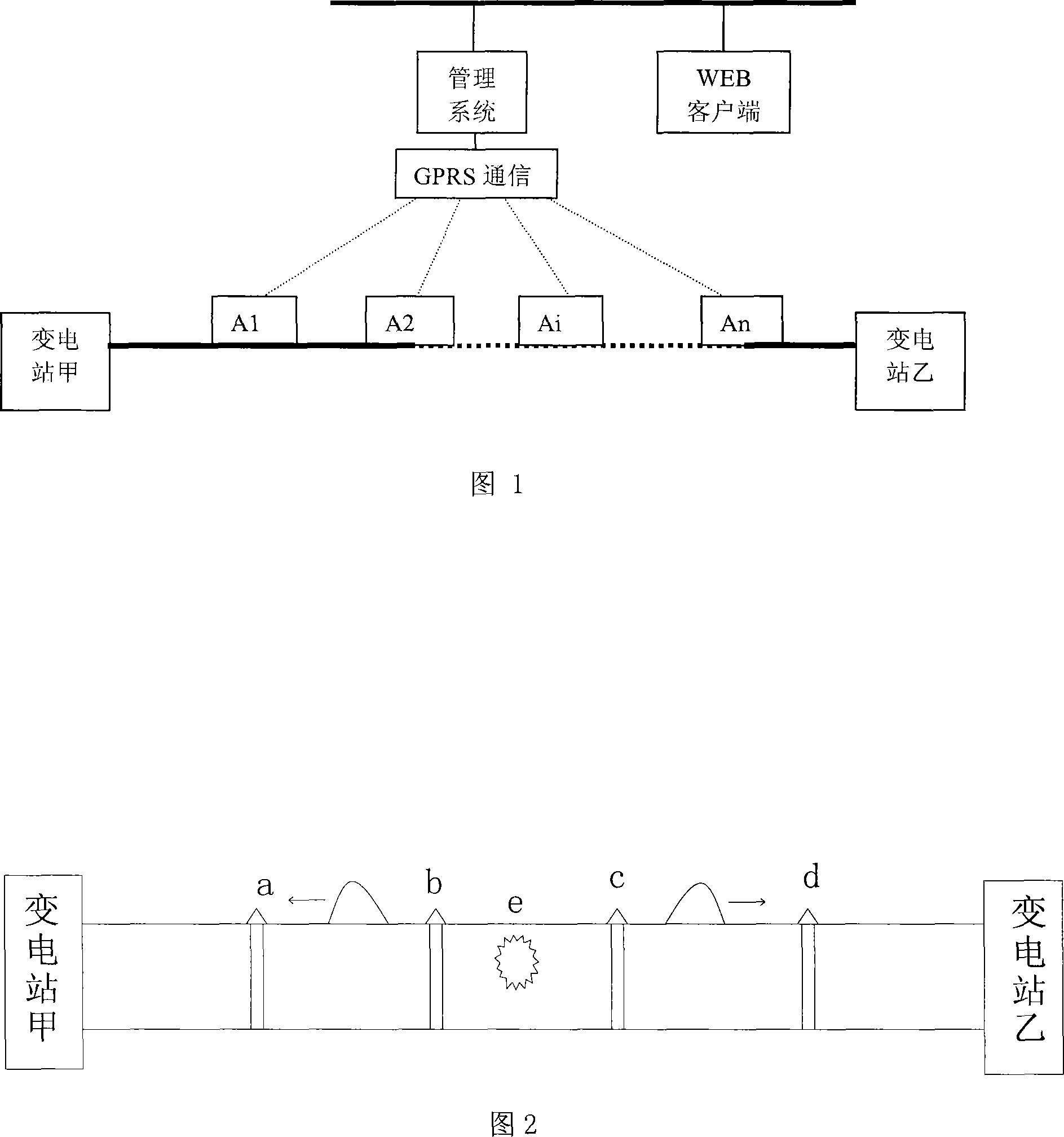
[0022] Example: There is a 50-kilometer-long 220kv transmission line between substation A and substation B of a power company in a certain area. There are many fault tripping accidents on this line, and a set of distributed high-precision transmission line traveling wave positioning system is installed to improve fault detection. positioning accuracy.

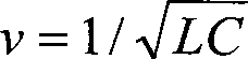
[0023] There are four on-site monitoring devices between substation A and substation B. These on-site monitoring devices are a, b, c and d at 10 kilometers, 20 kilometers, 30 kilometers and 40 kilometers from substation A. The device divides the wire between substation A and substation B into 5 sections. A fault occurs at point e on segment bc of the wire. The on-site monitoring device first receives the power frequency fault current propagating in the transmission line conductor, converts the power frequency fault current into a digital waveform signal through analog-to-digital conversion, and then uploads the digital wavefor...


PUM


Abstract

The invention provides an application method for a travelling wave positioning system of a distributed high-precision electric transmission line. The method comprises the following steps: receiving power frequency failure current transmitted in an electric transmission line wire by an on-site testing device, performing analog-to-digital conversion to the power frequency failure current to obtain digital waveform signals, uplinking the digital waveform signals to an upper computer, and determining the accurate position of trouble spot by a supervisory system installed in the upper computer via calculation. The method remarkably reduces the travelling wave positioning error and improves the positioning accuracy.

Description

technical field [0001] The invention relates to the field of power system fault location, in particular to the field of transmission line traveling wave location. Background technique [0002] With the expansion of the power system scale, the number of high-voltage transmission lines is increasing. The terrain of the area traversed by the high-voltage transmission line is complex and the weather conditions are harsh. It is extremely difficult to find the fault point after the fault occurs. In order to quickly and accurately locate the line after a fault occurs, repair the line in time and quickly restore power supply, for a long time, domestic and foreign scholars have studied many fault location principles and algorithms, and developed many fault location devices. Many of these fault location algorithms have high positioning accuracy in theory, but due to the uncertainty of the fault traveling wave velocity, the length of the transmission line is uncertain due to the influ...

Claims


Application Information

Patent Timeline
Patent Type & Authority Applications(China)
IPC IPC(8): G01R31/08
Inventor 钱冠军
Owner 钱冠军
Why Eureka
Try Eureka