AC contactor

A technology of AC contactors and moving contacts, which is applied in the direction of electrical components, electric switches, power devices inside switches, etc., which can solve the problems of slow arc movement speed, affecting arc extinguishing effect, and low magnetic field strength, so as to shorten arc extinguishing time, improve the breaking capacity, the effect of convenient wiring

Active Publication Date: 2011-11-09
ZHEJIANG PEOPLE ELE APPLIANCE
View PDF0 Cites 0 Cited by
  • Summary
  • Abstract
  • Description
  • Claims
  • Application Information

AI Technical Summary

Problems solved by technology

Studies have shown that the blowing arc magnetic field formed by the U-shaped arc striking angle has to pass through a long gap, the magnetic field strength is not high, and the arc movement speed is not fast, which affects the arc extinguishing effect to a certain extent
[0005] The coil assembly in a traditional contactor includes a skeleton for setting the coil and a coil arranged on the skeleton. The lead wire of the coil is generally electrically connected with the power line in the housing, and the terminal of the contactor is generally arranged in the housing. The disadvantage of the upper end is that if the control power supply is at the lower end of the contactor during complete wiring, the lead wire of the control power supply needs to be wound to the upper part of the contactor housing. The wiring is not only inconvenient, but also requires a long external wire, causing waste

Method used


Image

  • AC contactor
  • AC contactor
  • AC contactor

Examples


Embodiment 1

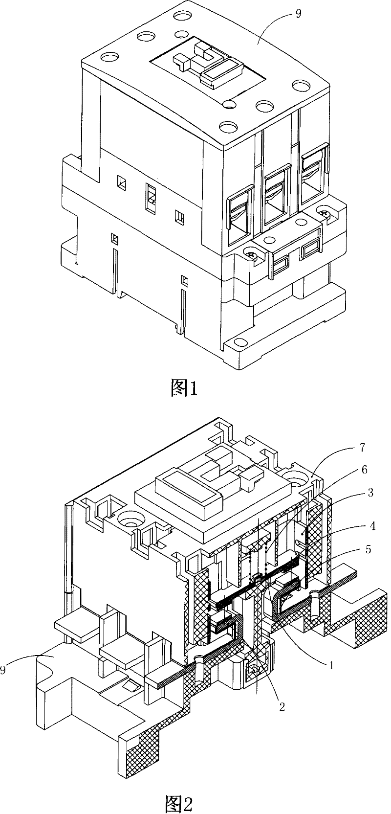
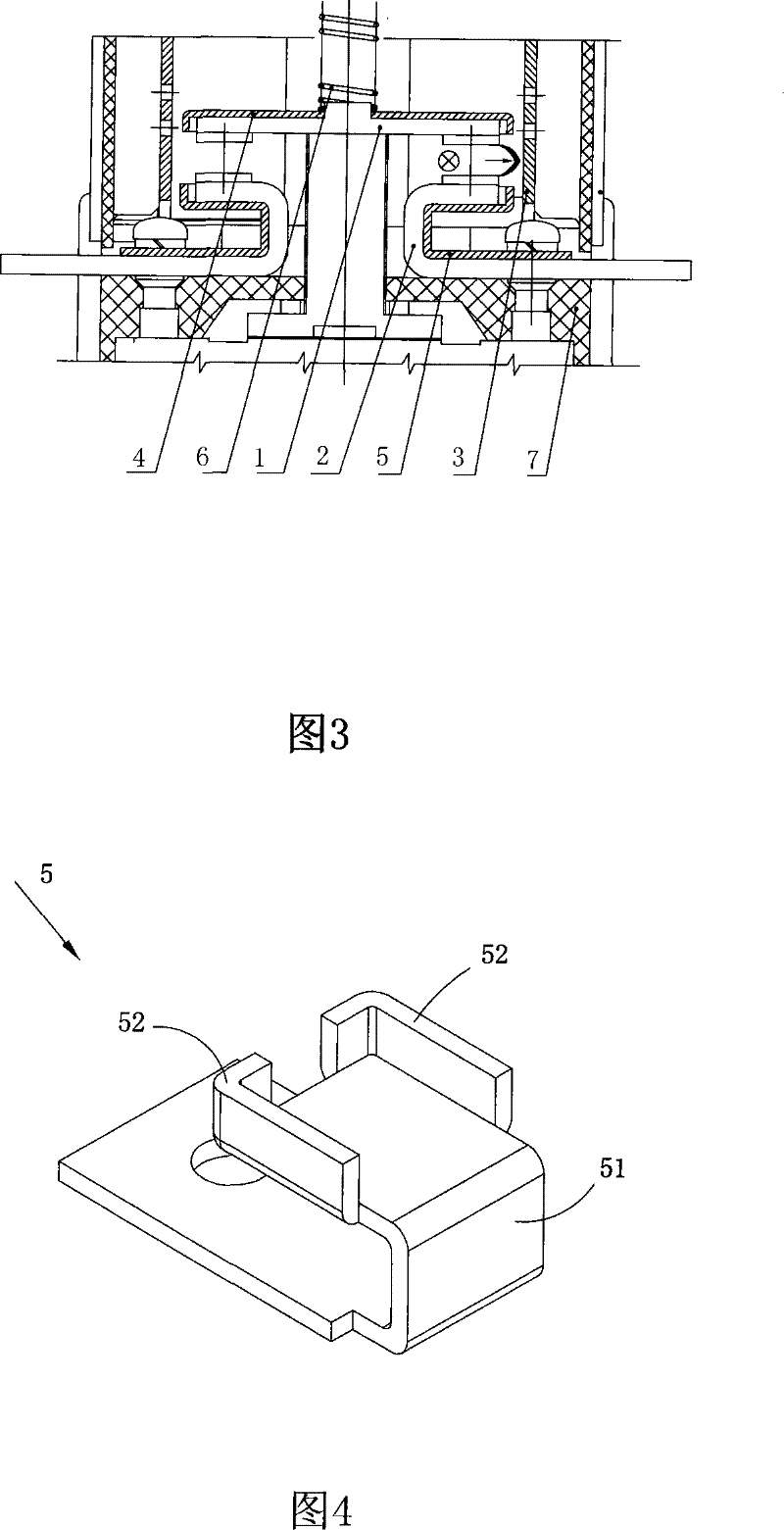
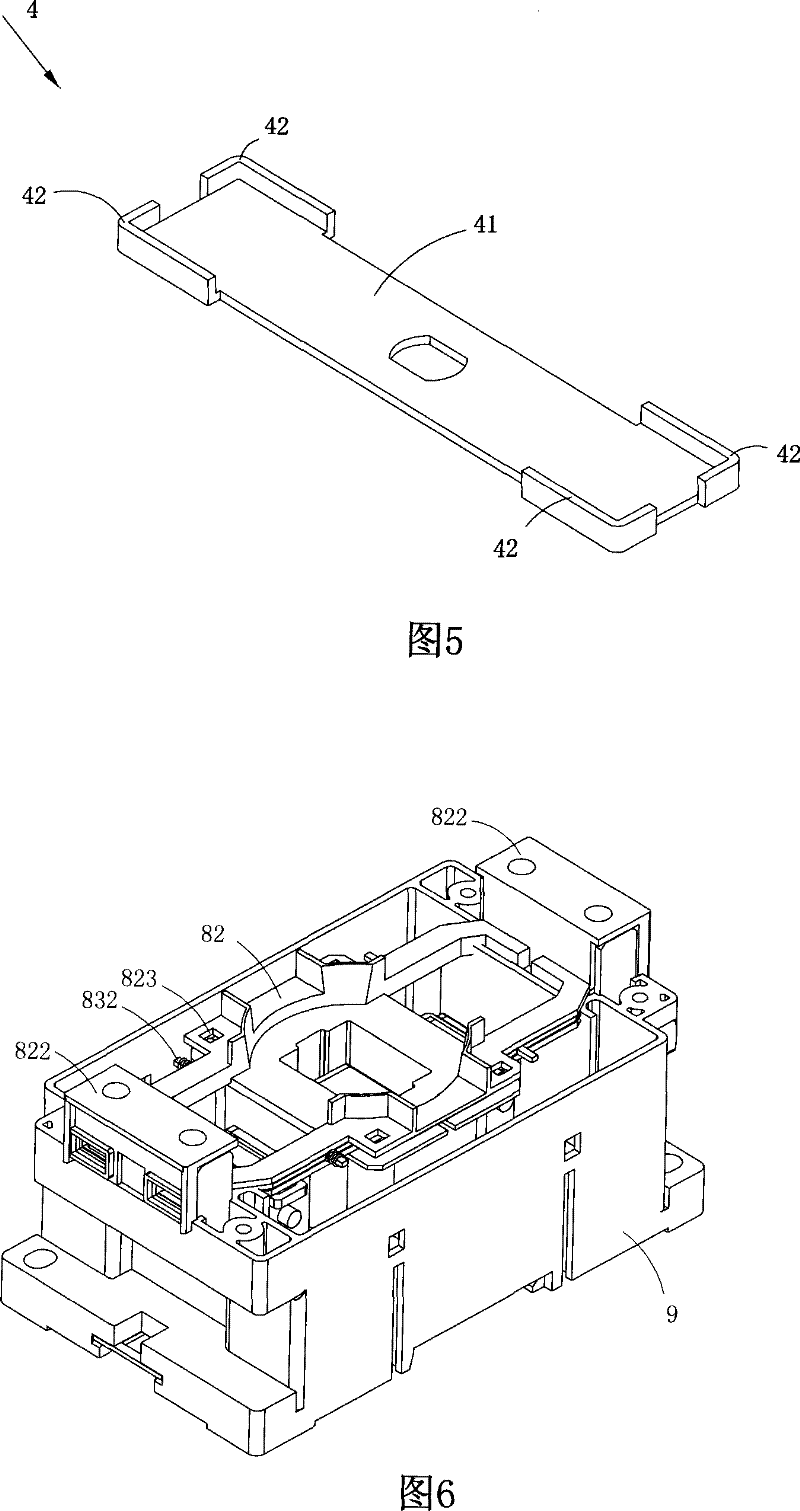
[0032] Figure 1 to Figure 12 A specific embodiment of the invention is shown in which figure 1 It is a schematic diagram of a three-dimensional structure of the present invention; figure 2 Yes figure 1 A schematic diagram of a three-dimensional structure of the arc extinguishing device in the AC contactor shown; image 3 Yes figure 1 The schematic diagram of the cross-sectional structure of the arc extinguishing device in the shown AC contactor; Figure 4 Yes figure 1 A schematic diagram of the three-dimensional structure of the first arc striker in the arc extinguishing device of the AC contactor shown; Figure 5 Yes figure 1 The schematic diagram of the three-dimensional structure of the second arc striker in the arc extinguishing device of the AC contactor shown; Image 6 Yes figure 1 The schematic diagram of the installation position of the coil device in the AC contactor shown; Figure 7 Yes figure 1 A schematic diagram of a three-dimensional structure of the ...


PUM


Abstract

The invention discloses an AC contactor, which comprises an arc suppressing device and a coil device. The arc suppressing device comprises a moving contact, two U-shaped static contacts and arc suppressing mechanisms arranged on both sides of the moving contact. The invention is structurally characterized in that the U-shaped slot of each static contact is provided with a first arc striking part basically in U shape which is used for increasing the magnetic field intensity. The first arc striking part comprises a U-shaped platelike body, and an arc striking part which protrudes towards the direction of the moving contact and is arranged on one end of the body of the first arc striking part. The invention can increase the magnetic field intensity effectively, thus increasing the velocity of movement of electric arc and the arc suppressing results.

Description

technical field [0001] The invention belongs to the technical field of electrical product structure design, and in particular relates to an AC contactor. Background technique [0002] U-shaped arc ignition angle arc extinguishing is to use ferromagnetic U-shaped arc ignition angle to form a magnetic field in the contact area when the contact is disconnected, driving the arc to move outward; when the arc forms four series of short arcs and the current crosses zero , using the near-pole effect to effectively extinguish the arc without re-ignition. [0003] Because of its simple structure and good arc extinguishing performance, the U-shaped arc extinguishing device can better protect the arc extinguishing cover and prevent it from being burned directly by the high temperature of the arc, so the U-shaped arc extinguishing device is used. Arc extinguishing devices are widely used in small-capacity AC contactors. [0004] So far, all foreign AC contactors that use U-shaped arc-t...

Claims


Application Information

Patent Timeline
Patent Type & Authority Patents(China)
IPC IPC(8): H01H9/34H01H9/44H01H3/28H01H9/12
Inventor 董仁勇黄章武
Owner ZHEJIANG PEOPLE ELE APPLIANCE
Why Eureka
Try Eureka