Blocking type electric engine iron core and manufacturing method thereof

A manufacturing method and block-based technology, applied in the manufacture of stator/rotor body, magnetic circuit shape/style/structure, salient poles, etc., can solve the problems of complicated processing, troublesome assembly, increased production costs, etc., and save silicon steel materials , high positioning accuracy and easy assembly

Inactive Publication Date: 2008-07-30
NINGBO POLARIS TECH
View PDF1 Cites 17 Cited by
  • Summary
  • Abstract
  • Description
  • Claims
  • Application Information

AI Technical Summary

Problems solved by technology

However, in said patent, when multiple sets of gear blocks are spliced ​​into an annular stator body, it is necessary to adopt fasteners (such as bolts, screws, etc. ) can be fixedly connected into one ...

Method used


Image

  • Blocking type electric engine iron core and manufacturing method thereof
  • Blocking type electric engine iron core and manufacturing method thereof
  • Blocking type electric engine iron core and manufacturing method thereof

Examples


Embodiment Construction

[0031] The present invention will be further described in detail below in conjunction with the accompanying drawings and embodiments.

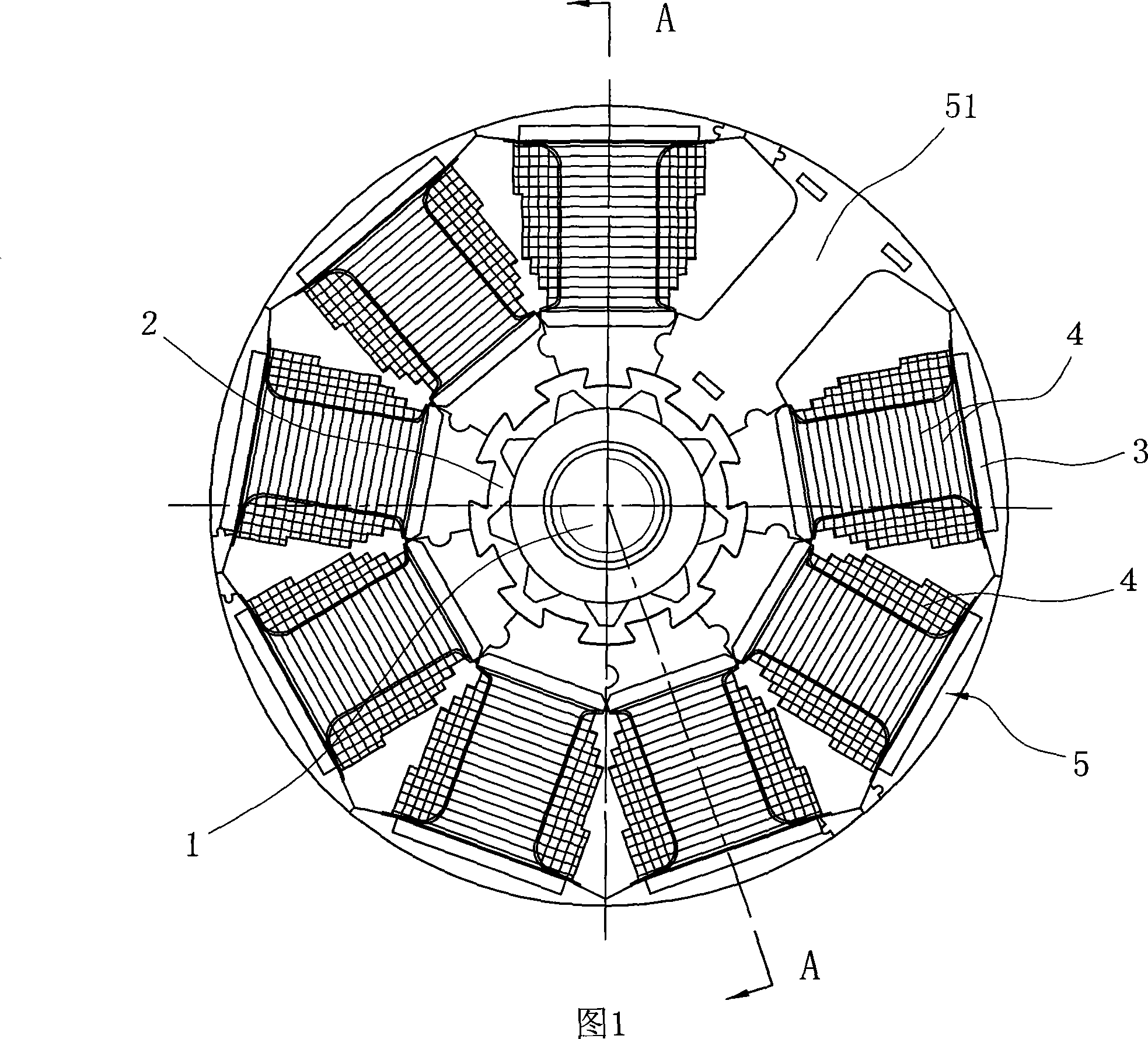
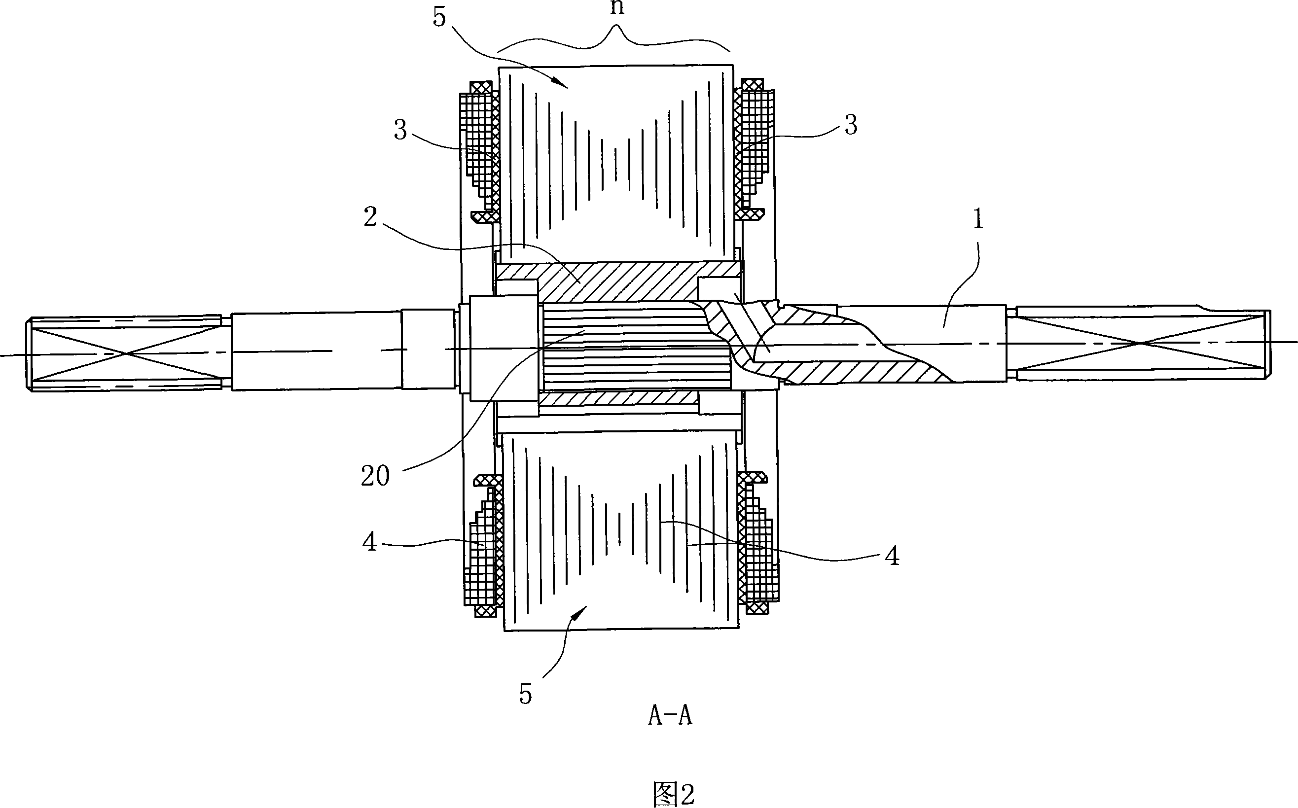
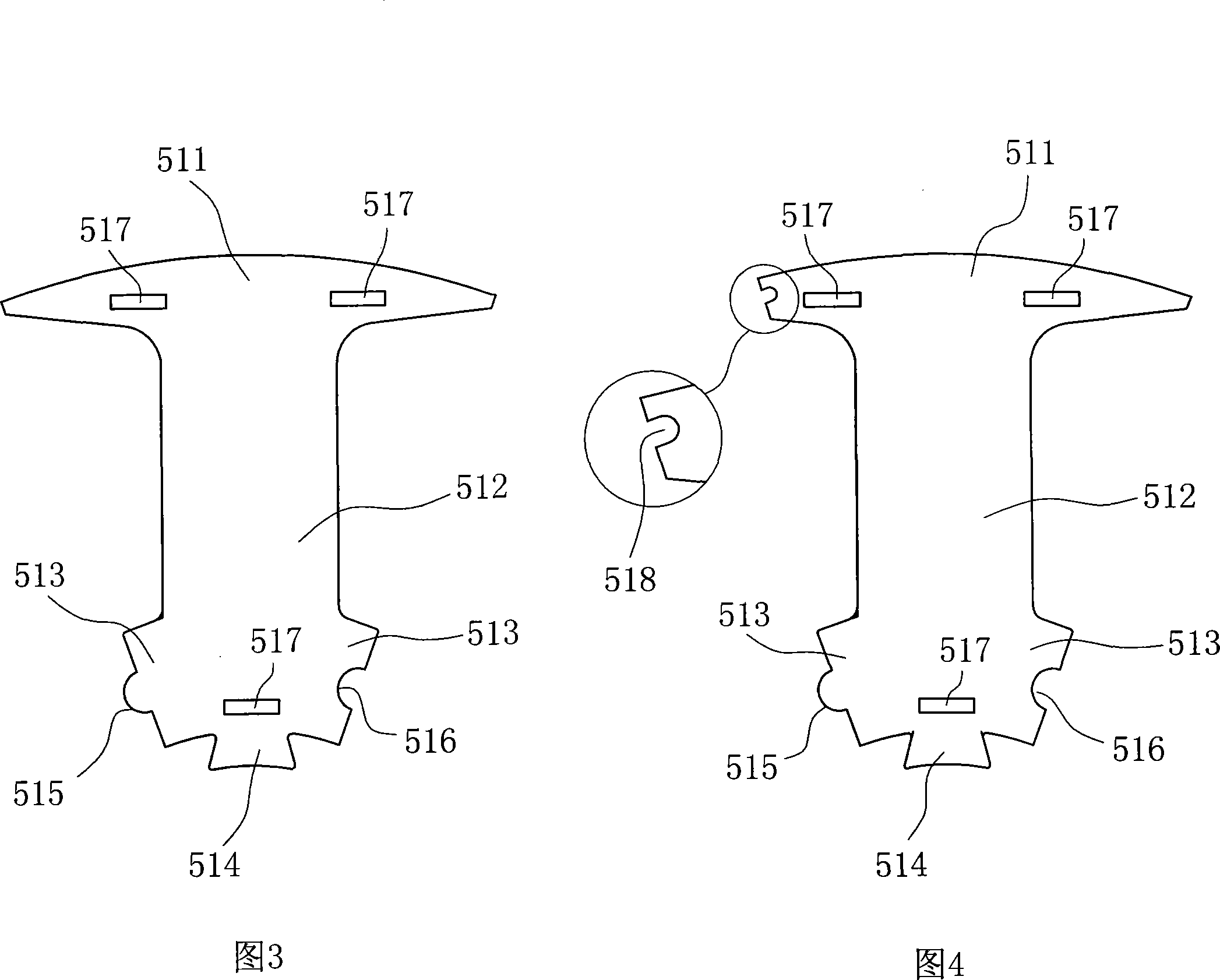
[0032] As shown in Figure 1 and Figure 2, it is a schematic structural diagram of the motor shaft assembly of the embodiment of the present invention, including a motor shaft 1, a positioning bracket 2 sleeved on the motor shaft, and a motor core fixed on the positioning bracket 2 , wherein, the motor iron core is positioned on the motor shaft 1 through the positioning bracket 2, the iron core is spliced ​​by 9 groups of segmented gear blocks 5 wound with coils 4, and the stamping thickness of each group of segmented gear blocks 5 n are all the same, and are respectively composed of 88 fan-shaped punches 51 of each 0.5mm pressed against each other, see Fig. The coil 4 and the outer ring of the positioning bracket 2 are provided with a fastening structure that is compatible with each group of segmental tooth blocks 5, and the segmental tooth bl...


PUM


Abstract

A separated iron core comprises a plurality of sector-shaped tooth block groups spliced with each other, wherein windings can be wound on the sector-shaped tooth block; and each sector-shaped tooth block group consists of a plurality of sector-shaped punching sheets stacked on each other. The iron core is characterized in that each sector-shaped punching sheet is a single-tooth sheet including a tooth crown, a tooth body and a yoke portion with an engagement section; each sector-shaped punching sheet further comprises a dovetail protrusion portion with a narrow upper portion and a wide lower portion extending on the bottom of the tooth body; and a dovetail groove section with wide bottom and narrow opening can be formed between the protrusion portions of two sector-shaped punching sheets correspondingly engaged with each other. The invention can improve the material utilization rate by stamping individually and stacking together; the dovetail protrusion portion is designed on the bottom of the tooth body of single sector-shaped punching sheet and the dovetail groove is formed between two engaged sector-shaped punching sheets; and the sector-shaped tooth block can be clamped on a positioning stand with matched tooth socket structure through the groove structure without fixing of bolts and via-holes, thus achieving simple structure, convenient assembly and high positioning accuracy.

Description

technical field [0001] The invention belongs to the technical field of motor manufacturing, and in particular relates to a motor iron core that can be assembled in blocks and a manufacturing method thereof. The motor iron core can be used not only as an inner stator core of a motor but also as a rotor of a generator iron core. Background technique [0002] At present, the iron core of the motor is usually processed by stamping lamination method or winding method. Among them, the winding method is only suitable for processing narrow ring cores with large curvature radius and relatively shallow slots, and is mainly suitable for inner open slots, such as automobile generator cores, but for cores with small radius and outer open slots Ordinary winding processing methods cannot be realized. Therefore, the general iron core adopts the method of stamping and lamination. The basic steps are: first, according to the cross-sectional shape of the iron core, punch the silicon steel sh...

Claims


Application Information

Patent Timeline
IPC IPC(8): H02K1/06H02K1/08H02K15/02
Inventor 晁会岩罗大铖
Owner NINGBO POLARIS TECH
Why Eureka
Try Eureka