
Fan and motor thereof

A technology for motors and bearing housings, applied in the field of fans and their motors, which can solve problems such as inability to meet adjustment needs, weakening of the magnetic field, and influence on the characteristics of the motor 10, so as to improve reliability, reduce distance, and avoid component wear and noise Effect

Active Publication Date: 2008-07-30
DELTA ELECTRONICS INC
View PDF0 Cites 7 Cited by
  • Summary
  • Abstract
  • Description
  • Claims
  • Application Information

AI Technical Summary

Problems solved by technology

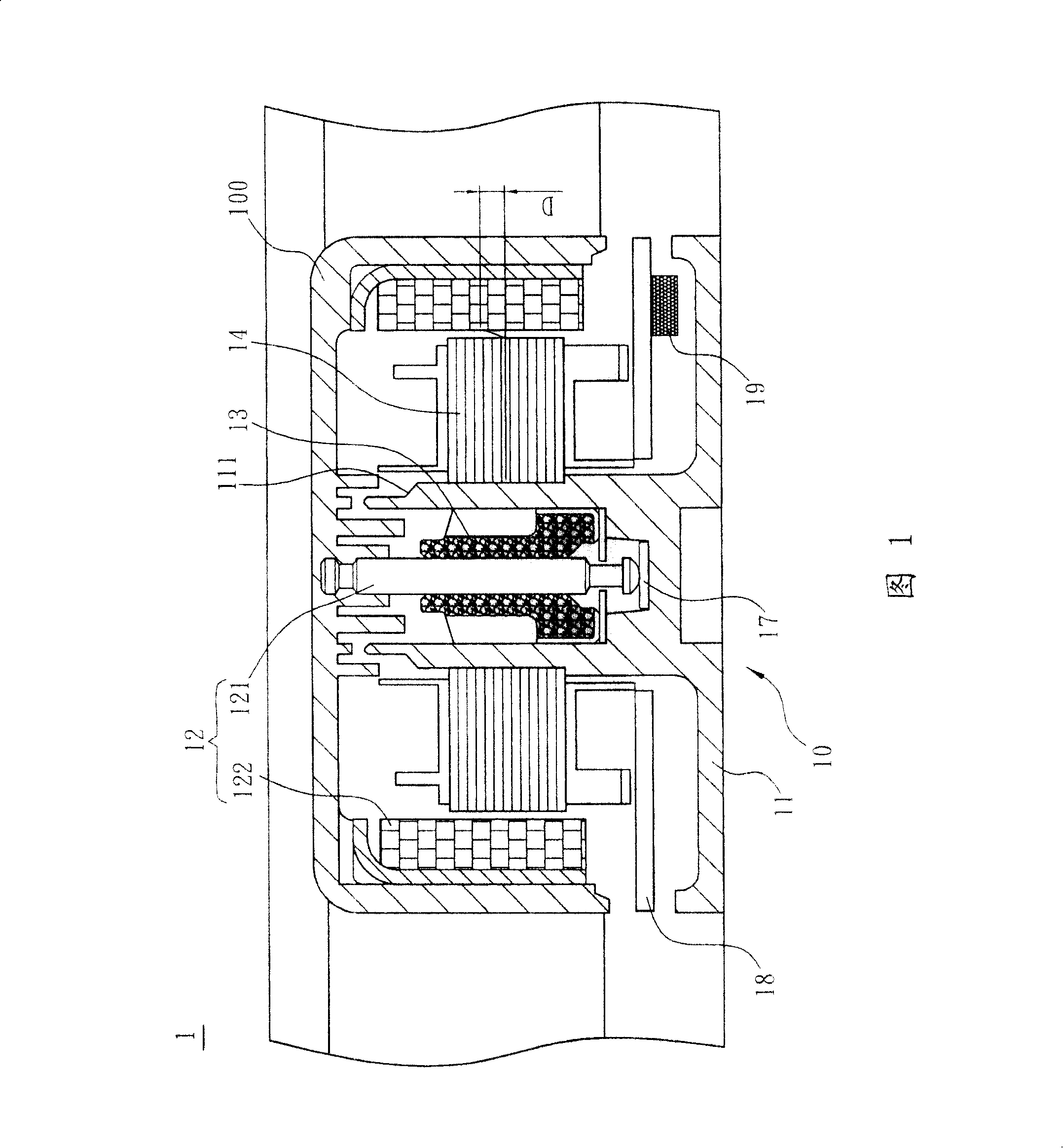
[0005] However, due to structural limitations, the adjustment of the magnetic offset D has a certain range, which cannot meet the needs of adjustment
And if the magnetic offset D is too large, electrical switching noise (Switch Noise) will be generated to form noise, and the distance between the Hall element 19 arranged on the circuit board 18 and the rotor 12 will be increased, so that the Hall element 19 can sense The magnetic field is weakened, thereby affecting the characteristics of the motor 10 (such as current waveform and speed, etc.)

Method used


Image

  • Fan and motor thereof
  • Fan and motor thereof
  • Fan and motor thereof

Examples


Embodiment Construction

[0026] A fan and its motor according to preferred embodiments of the present invention will be described below with reference to related drawings, wherein the same components will be described with the same reference symbols.

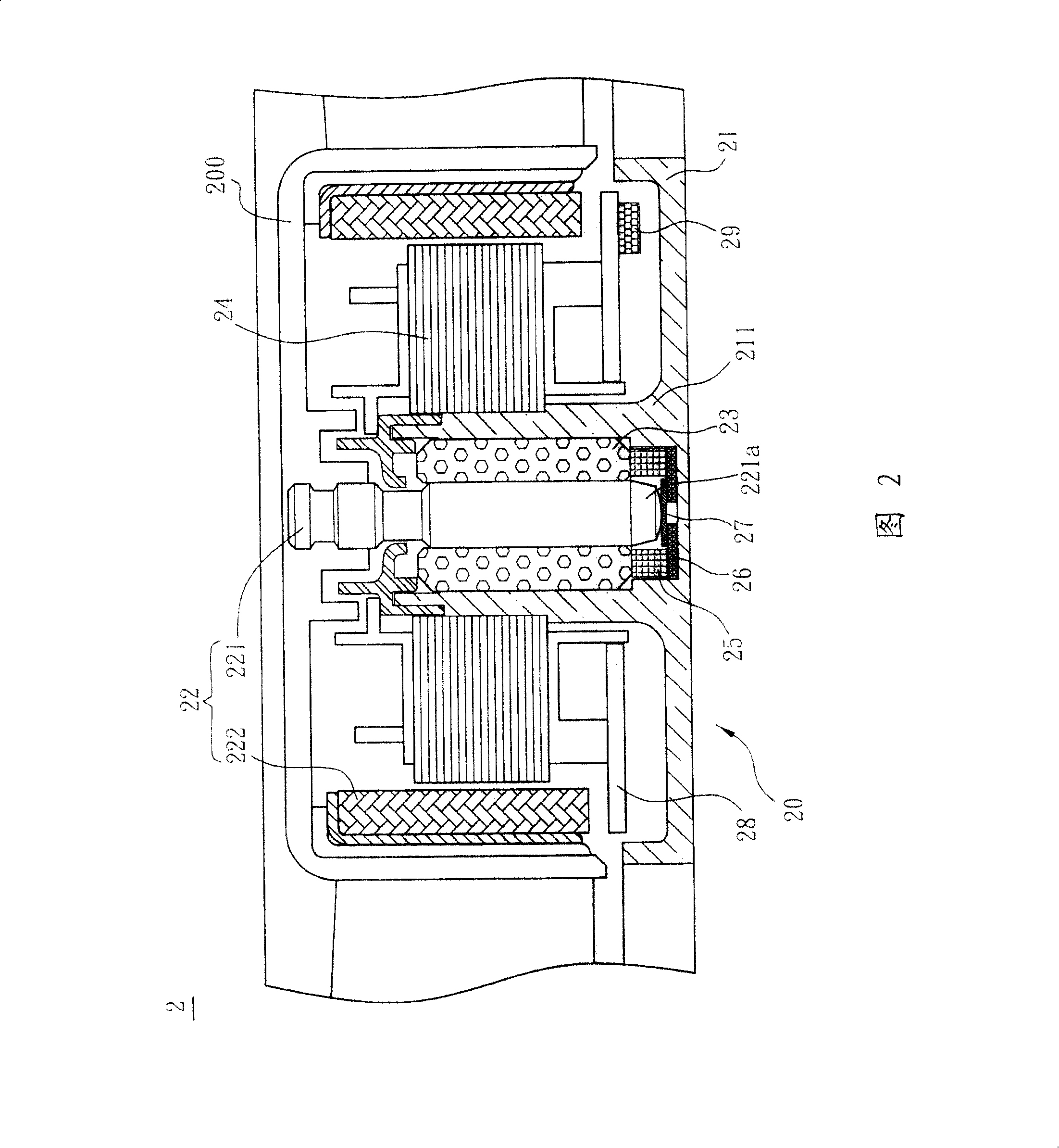
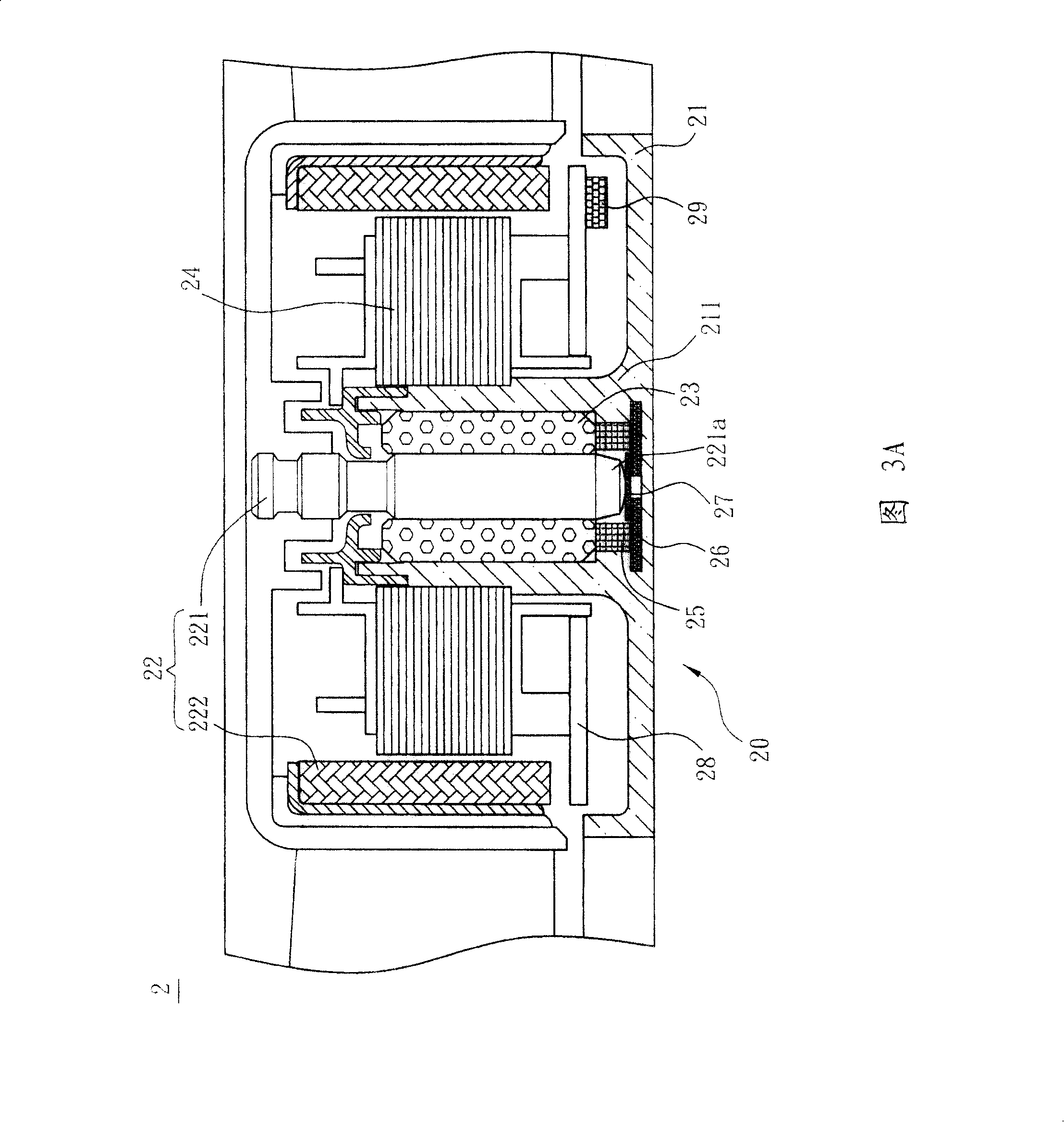
[0027] See also shown in Fig. 2, a kind of fan 2 of preferred embodiment of the present invention comprises a motor 20 and an impeller 200, and motor 20 drives impeller 200 to rotate, and motor 20 comprises a base 21, a bearing 23, a stator 24, a The rotor 22 and a magnetic body 25 . The center of the base 21 extends to form a bearing seat 211, the bearing 23 is accommodated in the bearing seat 211, the stator 24 is placed on the outer periphery of the bearing seat 211, the rotor 22 has a rotating shaft 221 and a magnetic ring 222, the magnetic ring 222 and The stator 24 is arranged correspondingly. The stator 24 is formed by winding a plurality of silicon steel sheets with a coil, and the rotating shaft 221 is passed through and installed on the bearin...


PUM


Abstract

The invention discloses a fan, which comprises a motor and an impeller, wherein the motor drives the impeller to rotate, and the motor comprises a base seat, a bearing, a stator, a rotor and a magnetic body. The central part of the base seat extends to form a bearing support; the bearing is arranged inside the bearing support; the stator is sleeved on the outer circumference of the bearing support; the rotor and the stator correspond to each other; a rotating shaft passes through the bearing; the magnetic body is arranged at the bottom of the bearing support, and is positioned close to one end of the rotating shaft.

Description

technical field [0001] The invention relates to a fan and its motor, in particular to a fan and its motor for maintaining stable and balanced operation of the rotor. Background technique [0002] When the fan is running, the force from the outside or the reaction force of the airflow to the rotor will cause the rotor to move outward, causing the rotor to vibrate up and down, causing the balance position to change, and mechanical interference with internal components or external components, resulting in noise and components. Wear and tear, and the outward movement of the rotor will increase the distance between the rotor and the magnetic induction element, affecting the induction performance of the magnetic induction element to the magnetic field. [0003] Please refer to FIG. 1 , in order to solve this problem, a conventional fan 1 includes a motor 10 and an impeller 100 , and the motor 10 drives the impeller 100 to rotate. The motor 10 includes a base 11 , a rotor 12 , a b...

Claims


Application Information

Patent Timeline
Patent Type & Authority Applications(China)
IPC IPC(8): H02K7/00H02K7/09F16C17/10F16C32/04H02K5/22H02K29/08F04D25/08
Inventor 林永彬叶东昌马晓林胡应喜段勇
Owner DELTA ELECTRONICS INC
Learn More