Elevating conveyance device

A technology of conveying device and lifting drive mechanism, which is applied in the direction of lifting device, lifting frame, transportation and packaging, etc., which can solve the problems of rising equipment cost, lack of versatility, and inability to use flexibly

Active Publication Date: 2008-08-06
DAIFUKU CO LTD
View PDF1 Cites 17 Cited by
  • Summary
  • Abstract
  • Description
  • Claims
  • Application Information

AI Technical Summary

Problems solved by technology

[0003] The elevating and conveying device in the form of a table lifter and the elevating and conveying device for transfer in the form of a multi-joint robot do not need to be designed and arranged in any respect, as long as it is a solid floor, they can be installed freely and used flexibly. If the transfer point is small, it cannot be used flexibly
However, in the lifting transport device for transfer in the form of an articulated robot, the degree of freedom of the transfer path is high, but there is a disadvantage that the cost of equipment is greatly increased.
In contrast to this situation, in the lifting and conveying device in the form of a descending lifter described in Japanese Patent Application Laid-Open No. 58-92221, the head is increased, but the top of the pillar must be connected and supported with the beams on the patio side, and it cannot be simply installed on the floor
Namely, has the disadvantage of lacking versatility

Method used


Image

  • Elevating conveyance device
  • Elevating conveyance device
  • Elevating conveyance device

Examples


Embodiment Construction

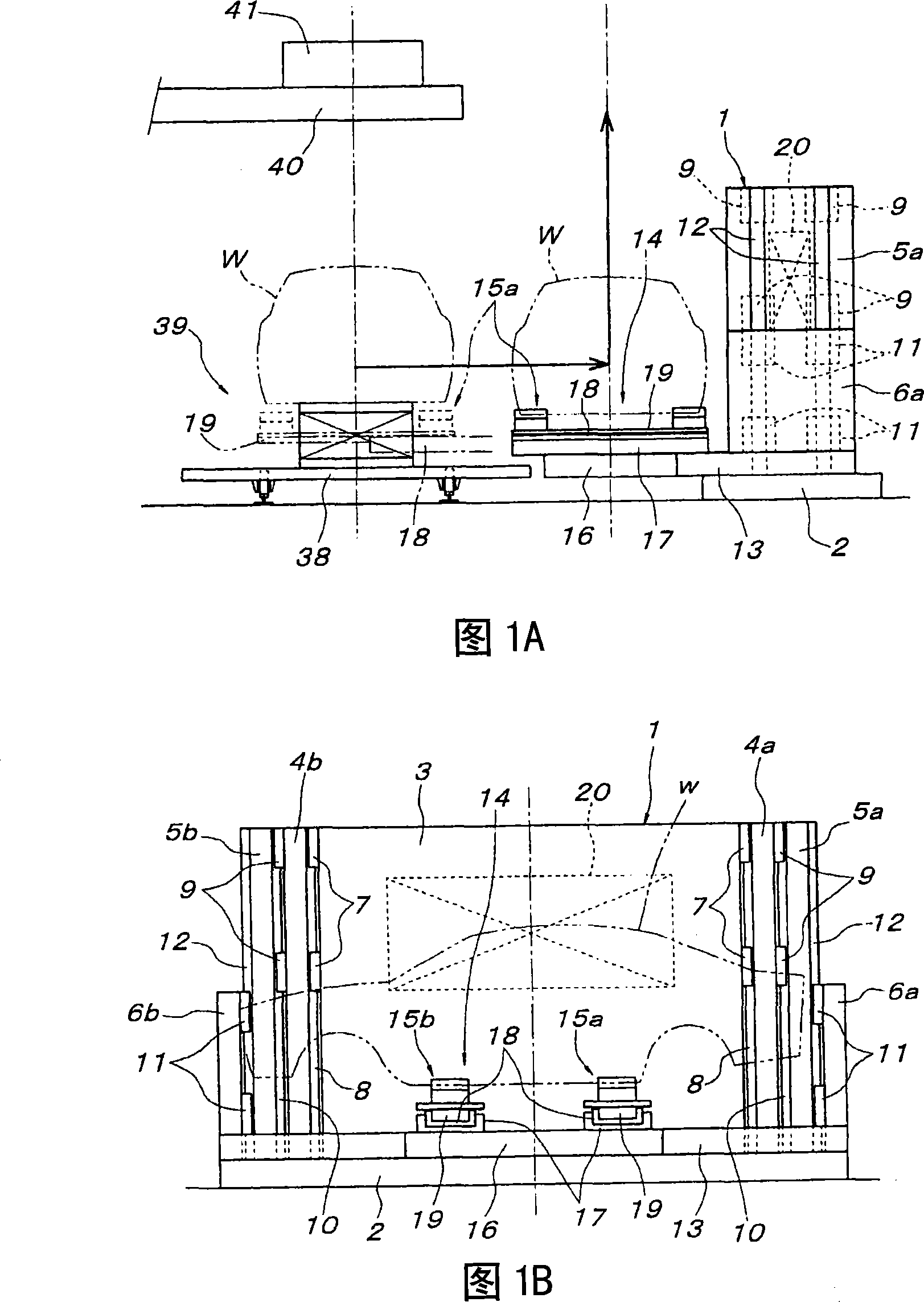
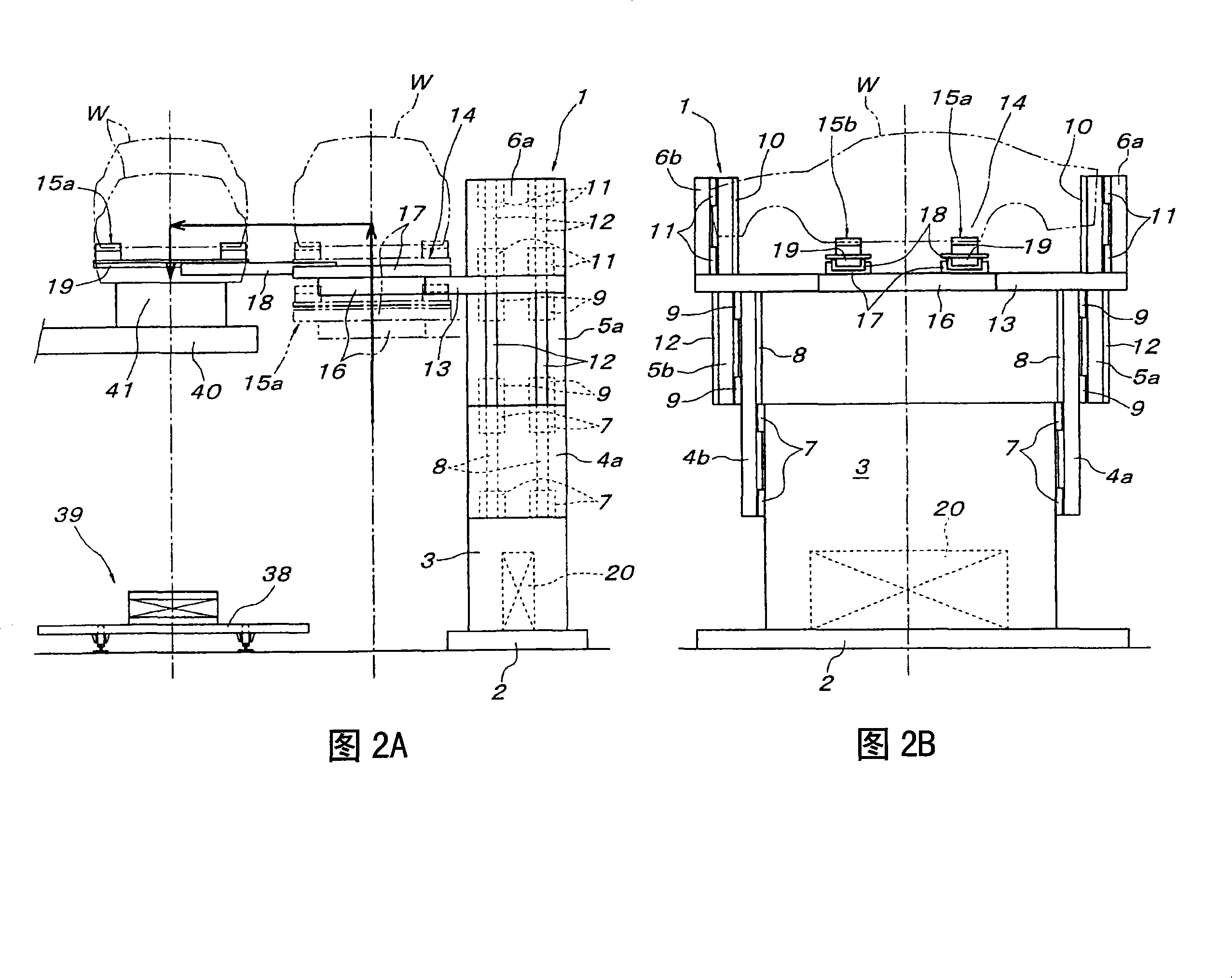
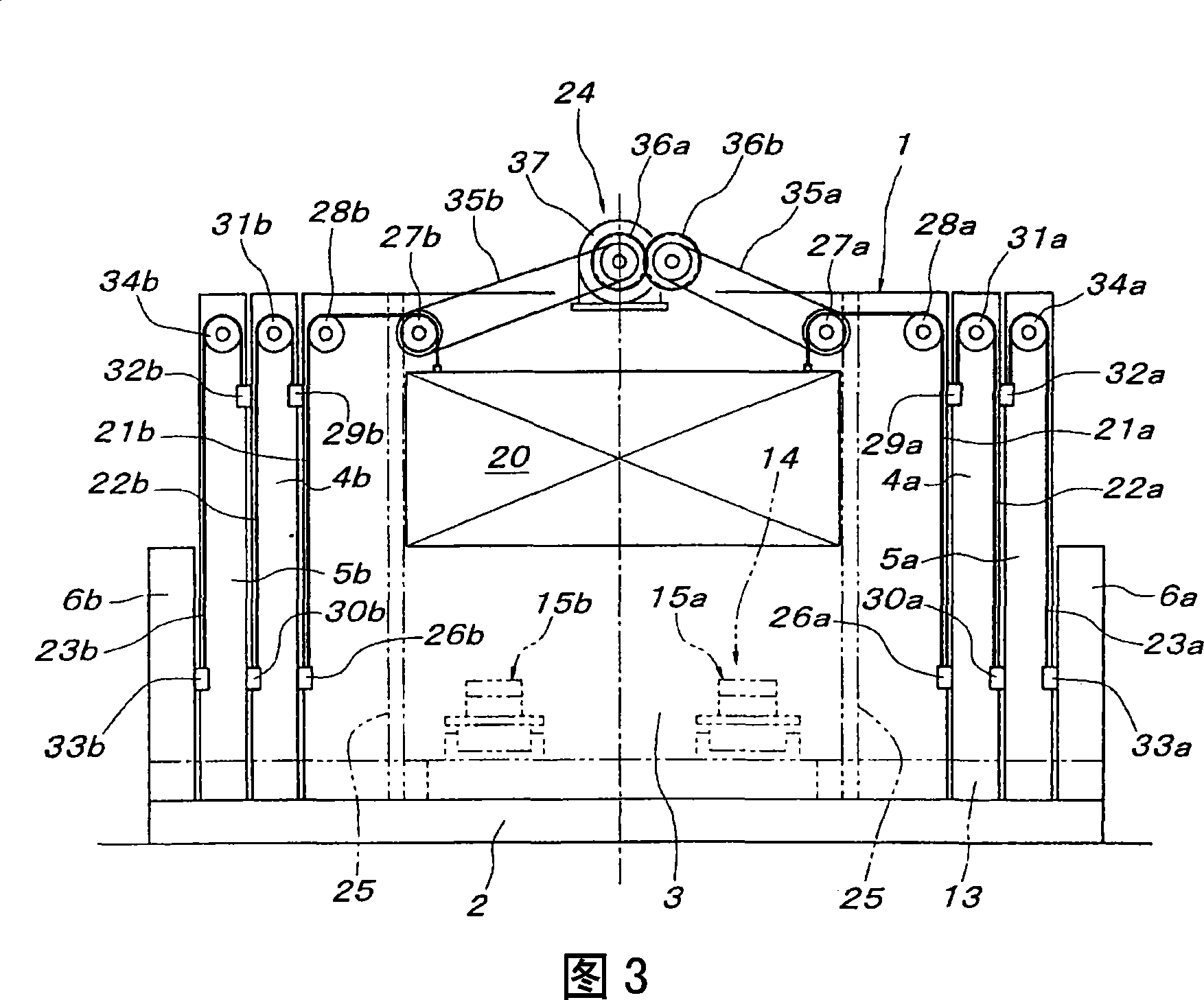
[0043] Below, according to Fig. 1~Fig. 3, the first embodiment when the present invention is implemented as a transfer device is described, and the reference number 1 represents a multi-section telescopic strut body, which is erected on the floor surface and fixed by an anchor or the like on the base 2. Fixed pillar portion 3; a pair of left and right first middle section lifting pillar portions 4a, 4b supported on the left and right sides of the fixed pillar portion 3 in a liftable manner; A pair of left and right middle section lifting support parts 5a, 5b on the outside of the pillar parts 4a, 4b; a pair of left and right bottom joint lifting parts 6a, 6b constitutes. The planar shape of the fixed pillar portion 3 is a rectangular column shape that is long in the lateral direction.

[0044] The elevating and guiding mechanism of each elevating strut portion 4a-5b and the last elevating portion 6a, 6b can be arbitrary, but, in this embodiment, a pair of left and right first...


PUM


Abstract

The present invention provides a lifting and conveying device, which can improve the versatility of the lifting and conveying device that can be used in the transfer of automobile bodies in automobile assembly lines. The multi-section telescopic pillar body includes a fixed pillar part, at least one middle-section lifting pillar part, and a last-section lifting part. The transfer mechanism is arranged on the last-section lifting part. The inner lifting balance weight acts upward on the weight of the balance weight on the winding transmission part on the middle lifting pillar of the next section, and the lifting and lowering driven by the middle lifting pillar of the next section relative to the fixed pillar. The drive mechanism is composed of winding transmission parts that transform the rising motion of the middle lifting pillar part into the rising movement of the middle lifting pillar part or the last lifting part of the next stage.

Description

technical field [0001] The present invention relates to an elevating and conveying device that can be utilized for transferring automobile bodies in an automobile assembly line, and the like. Background technique [0002] As the lifting and conveying device that can be used for the transfer of automobile body etc., it is known that there is a device for loading a transfer mechanism that can move forward and backward in the horizontal direction on the lifting table of the table lifter form; As described, a descending lifter-type device in which a moving mechanism capable of advancing and retreating in the horizontal direction is mounted on a lifting body that can be raised and lowered along the pillar. In addition, lifting transport devices in the form of articulated robots are known which can be used for transfer devices. [0003] The elevating and conveying device in the form of a table lifter and the elevating and conveying device for transfer in the form of a multi-joint...

Claims


Application Information

Patent Timeline
Patent Type & Authority Applications(China)
IPC IPC(8): B66F7/04B62D65/18B65G47/52
Inventor 京谷尚士
Owner DAIFUKU CO LTD
Why Eureka
Try Eureka