Glass pipe cutting device

A cutting device and technology for glass tubes, applied in the field of tube cutting devices, can solve problems such as unstable product quality, low efficiency, broken glass tubes, etc., and achieve the effects of not being easily broken, stable product quality, and high production efficiency

Inactive Publication Date: 2008-08-06
李家凌
View PDF0 Cites 21 Cited by
  • Summary
  • Abstract
  • Description
  • Claims
  • Application Information

AI Technical Summary

Problems solved by technology

Then just can continue to cut, and like this, glass tube section just is cut off, and the work of existing split glass tube is to carry out with m

Method used


Image

  • Glass pipe cutting device
  • Glass pipe cutting device
  • Glass pipe cutting device

Examples


Embodiment Construction

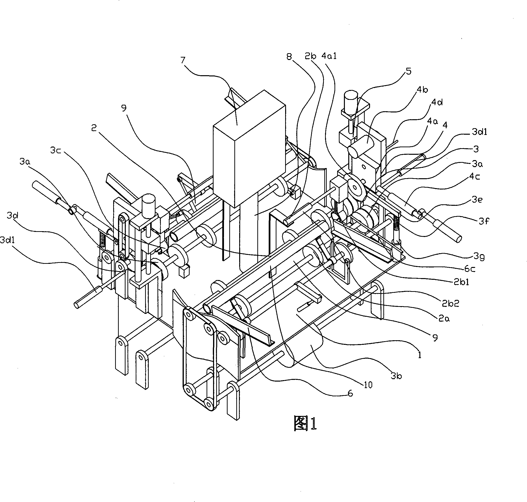
[0013] Now in conjunction with accompanying drawing and embodiment the present invention is described in further detail:

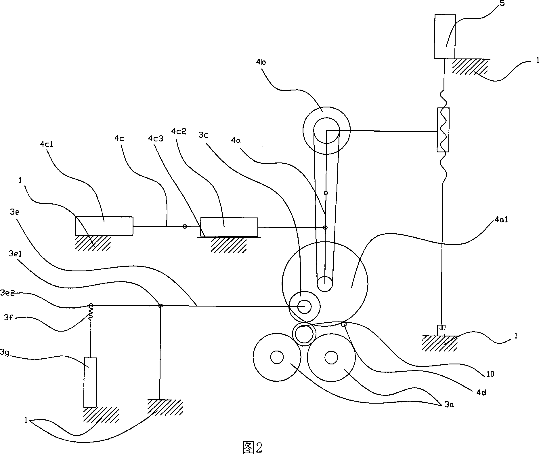
[0014] As shown in Figure 1, the present invention is made up of glass tube conveying device 2, glass tube positioning device 3, glass tube cutting device 4, control device 7 that are arranged on frame 1, and glass tube conveying device 2 consists of conveying track 2a, setting The glass tube pinching device 2b on the conveying track 2a is composed of a glass tube pinching device 2b consisting of a clip 2b1 and a power device 2b2 that drives the clip 2b1 to move back and forth. Wheel 3a, the transmission wheel power mechanism 3b that drives the transmission wheel 3a to rotate, the pressure wheel 3c positioned at the top of the transmission wheel 3a, and the positioning baffle 3d in front of the transmission wheel 3a constitute, and the positioning baffle 3d is connected with the piston rod of the positioning cylinder 3d1, In order to control the position o...


PUM


Abstract

The invention relates to a device for cutting a glass tube, which is characterized by comprising a glass tube transferring device, a glass tube positioning device, a glass tube cutting device and a controlling device on a chassis, wherein, the glass tube transferring device consists of a transferring orbit and a glass tube clamping and transferring device on the transferring orbit; the glass tube clamping and transferring device consists of a cramp and a power device driving the cramp to move forward and backward; the glass tube positioning device consists of a pair of driving wheels arranged on ends of the transferring orbit, a power mechanism of the driving wheels which drives the driving wheels to rotate, a pressing wheel above the driving wheels, and a positioning baffle in front of the driving wheels; the glass tube cutting device consists of a cutting flywheel knife mechanism arranged on the chassis in the manner of swinging, a flywheel knife power mechanism which is arranged on the chassis and drives the flywheel knife on the cutting flywheel knife mechanism to rotate, and a power swinging mechanism which drives the cutting flywheel knife mechanism to swing. Compared with the prior art, the device for cutting the glass tube has the advantages of high production efficiency, stable production quality, and little possibility of breaking the glass tube.

Description

Technical field: [0001] The invention relates to a pipe cutting device. Background technique: [0002] In the production of electric light sources, a large number of glass tube segments are required. The glass tube segments are obtained by cutting the glass tube into small segments. Due to the limitation of the nature of the glass tube, it is necessary to make marks on the glass tube before cutting. Then just can continue to cut, and like this, glass tube section just is cut off, and the work of existing split glass tube is to carry out with manual, and manually carry out not only efficient low, unstable product quality, and, easily because of operator's mistake, make glass tube broken. Invention content: [0003] The object of the present invention is to provide a glass tube cutting device with high production efficiency, stable product quality and unbreakable glass tube. [0004] The present invention is achieved in this way, and consists of a glass tube conveying devi...

Claims


Application Information

Patent Timeline
IPC IPC(8): C03B33/06
Inventor 李家凌
Owner 李家凌
Why Eureka
Try Eureka