Heat pump type heat exchanging unit

A technology of heat exchange units and heat pumps, applied in the energy field, to achieve the effects of reducing initial investment and water pump operation power consumption, reducing heating costs, and improving utilization efficiency

Active Publication Date: 2008-08-06
TSINGHUA UNIV +1
View PDF0 Cites 60 Cited by
  • Summary
  • Abstract
  • Description
  • Claims
  • Application Information

AI Technical Summary

Problems solved by technology

At present, the temperature of the hot water supply and return water in the central heating primary network is generally about 130-60°C. Among the

Method used


Image

  • Heat pump type heat exchanging unit
  • Heat pump type heat exchanging unit
  • Heat pump type heat exchanging unit

Examples


Embodiment 1

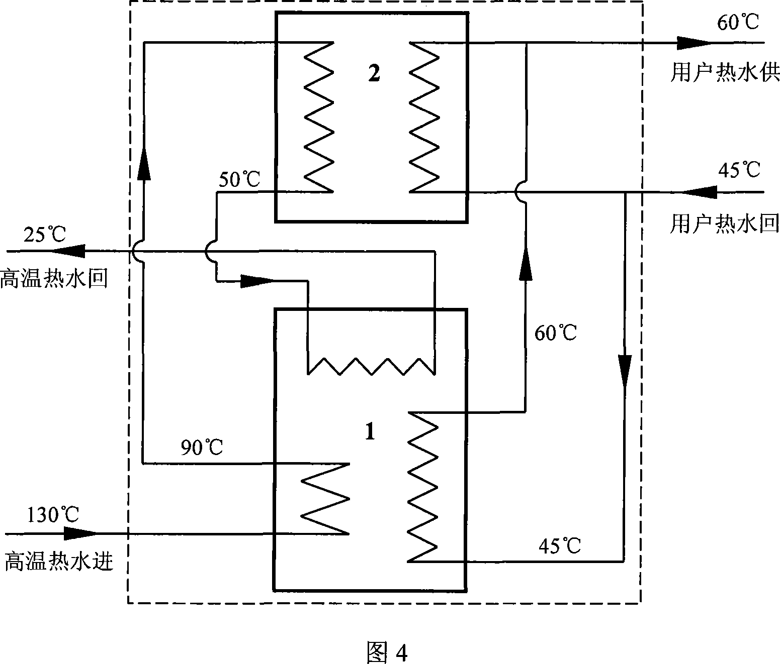
[0014] Embodiment 1: As shown in Figure 4, the unit is composed of a hot water absorption heat pump, a water-water heat exchanger and connecting pipeline accessories. The waterway system is divided into a primary side hot water pipeline and a secondary side hot water pipe Road in two parts. In actual operation, the hot water at 130°C on the high temperature side first enters the hot water absorption heat pump unit 1 as the driving energy, heats and concentrates the lithium bromide solution in its generator, and flows out of the hot water absorption heat pump 1 when it cools down to about 90°C. The hot water at 90°C enters the water-water heat exchanger 2 as a heating source, heats the hot water return water in the secondary network, and flows out of the water-water heat exchanger 2 when the temperature drops to 50°C, and the hot water at 50°C returns to the heat The water-type absorption heat pump 1 acts as a low-level heat source, which flows out after cooling down to about 2...

Embodiment 2

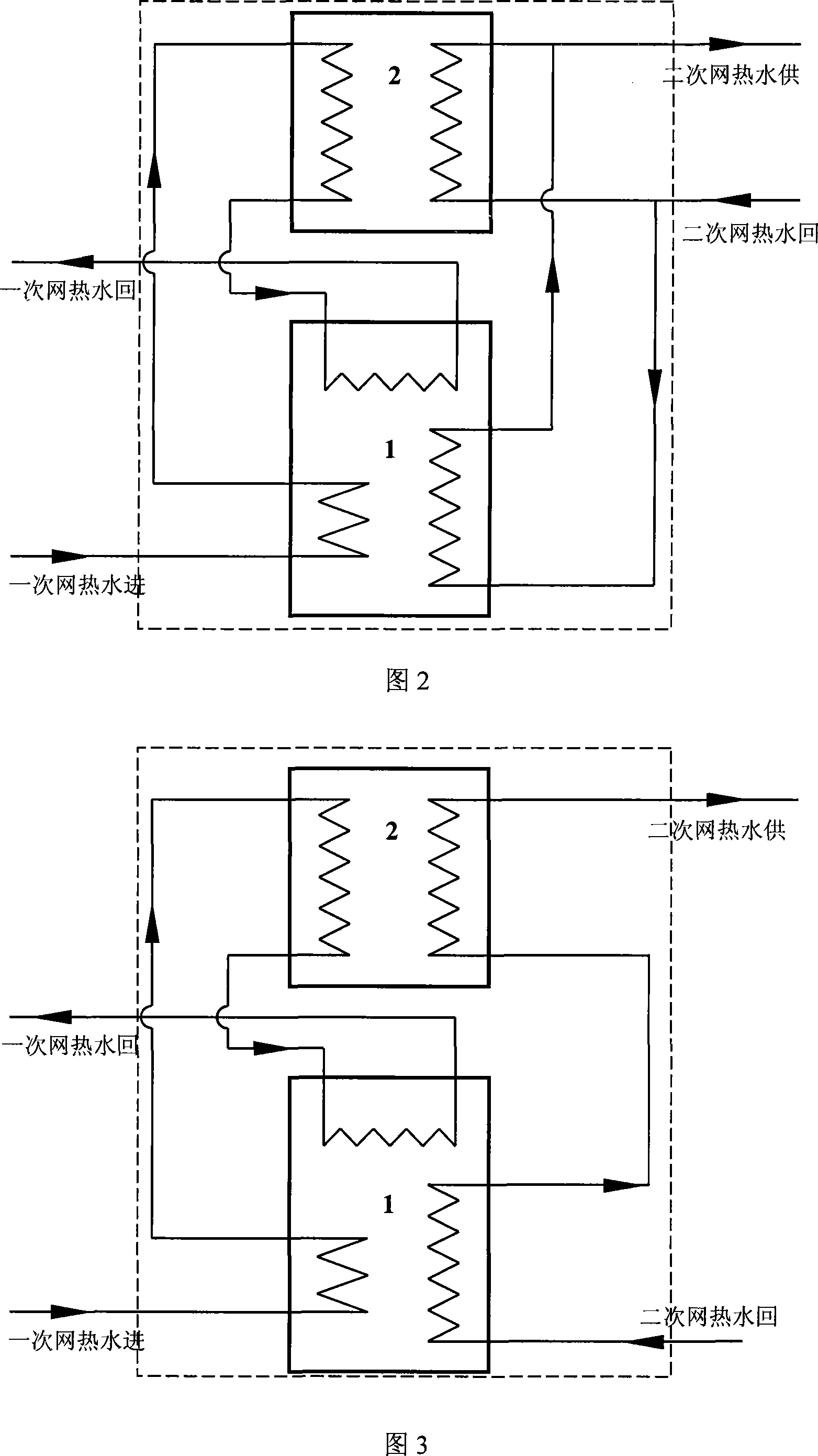
[0015] Example 2: Two-stage water-water heat exchangers in series heat pump heat exchange unit. As shown in Figure 5, the unit is composed of a hot water absorption heat pump, a primary water-water heat exchanger, a secondary water-water heat exchanger and connecting pipeline accessories. The water system is divided into primary side hot water pipelines and the secondary side hot water pipeline. In actual operation, the hot water at 130°C on the high temperature side first enters the hot water absorption heat pump unit 1 as the driving energy, heats and concentrates the lithium bromide solution in its generator, and flows out of the hot water absorption heat pump 1 when it cools down to about 90°C. The hot water at 90°C enters the secondary water-water heat exchanger 2b as a heating heat source, heats the hot water of the secondary network, flows out when the temperature drops to 65°C, and then enters the primary water-water heat exchanger 2a to add hot water of the secondary ...


PUM


Abstract

The invention relates to a heat pump type heat exchange units, which belongs to the technical field of energy. The units are composed of hot water type absorption heat pump units, a water-water heat exchanger, various connecting pipelines and accessories, wherein a water flow system of the connecting pipelines is divided into a primary side pipeline and a secondary side pipeline, the primary side pipeline employs a manner of a step sequence series connection, hot water of the primary side pipeline sequentially passes through a generator of an absorption heat pump, the water-water heat exchanger and an evaporator of the absorption heat pump, hot water of the secondary side pipeline passes through an absorption device and a condenser of the absorption heat pump and the water-water heat exchanger, because the primary side pipeline of the heat exchange units sequentially passes through the generator of the absorption heat pump, the water-water heat exchanger and the evaporator of the absorption heat pump, energy of hot water is used step by step, thereby greatly increasing differential temperature between water supply and water return of primary side hot water. Additionally, outlet water temperature of primary side heat exchange units is commonly lower than that of secondary side inlet water, which can not be realized by conventional heat exchanger.

Description

technical field [0001] The invention relates to a heat exchange unit for heating and hot water supply, in particular to a heat exchange device capable of greatly increasing the temperature difference between primary network hot water supply and return water in a central heating system, and belongs to the field of energy technology. Background technique [0002] With the continuous increase of the scale of urban central heating, high-temperature hot water produced by centralized heat sources often needs to be transported over a long distance to reach the heat user. Under the same heating load, the temperature difference between the supply and return water of hot water is increased. It can reduce the flow of hot water to be transported, thereby reducing the initial investment of transmission and distribution pipelines, and reducing the power consumption of water pumps during system operation. Therefore, it can save heating energy consumption and reduce heating costs. At presen...

Claims


Application Information

Patent Timeline
IPC IPC(8): F25B15/00F25B30/04
CPCF24D3/18Y02B30/12
Inventor 付林江亿张世钢肖常磊胡鹏狄洪发陈闯
Owner TSINGHUA UNIV
Why Eureka
Try Eureka