
Novel combined heat dissipation terminal system

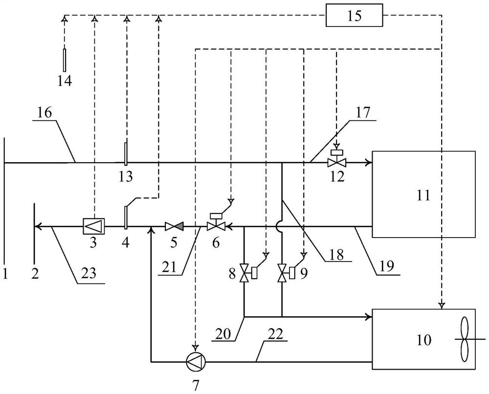
A new type of export-side technology, applied in the field of new combined heat dissipation terminal system, can solve the problems of reduced heat supply coefficient of air conditioning units, difficulty in large-scale promotion and use, and high operating costs, so as to reduce circulation flow and circulation pump power consumption, and save energy Significant benefits and reduced operating energy consumption

Active Publication Date: 2020-09-08
HEBEI UNIV OF TECH
View PDF12 Cites 1 Cited by
  • Summary
  • Abstract
  • Description
  • Claims
  • Application Information

AI Technical Summary

Problems solved by technology

However, when the outdoor temperature is low (at this time, additional supplementary heating is needed), the heat supply coefficient of the air conditioning unit decreases, and the same heat supply will consume more electric energy. At the same time, the outdoor unit as an evaporator also has frosting risk
The heat supply coefficient of the electric heater is slightly less than 1, which is significantly lower than that of the heat pump air conditioner. It will consume more electricity to obtain the same heat supply, and the operating cost is high, so it is difficult to promote and use it on a large scale.

Method used


Image

  • Novel combined heat dissipation terminal system
  • Novel combined heat dissipation terminal system
  • Novel combined heat dissipation terminal system

Examples


Embodiment 1

[0032] The use of this system can increase the temperature difference between the secondary network supply and the return water, and bring significant energy-saving benefits.

[0033] Suppose a heating power station supplies heat to 100 building users through the secondary network, and each household has a heating area of ​​150m 2 , The design heat index is 40W / m 2 ; At the same time, suppose that the design supply and return temperature of the secondary network is 60 / 50℃ (temperature difference 10℃).

[0034] Under the above calculation conditions, the mass flow rate of the circulating pump in the secondary network of radiant floor heating is:

[0035]

[0036] Assuming that the head of the secondary network circulating pump is 28m and the mechanical efficiency is 0.7, the electric power of the circulating pump is:

[0037]

[0038] When the system of the present invention is adopted and the third operating state of the radiation and convection hybrid heating mode is adopted, the retu...

Embodiment 2

[0043] Compared with conventional air source heat pump air conditioners and electric heaters, the electrically driven heat pump heater 10 in this system has the smallest energy consumption under the same heat output condition, and has a significant energy saving effect.

[0044] If 40% of the heat load of a building user is borne by electric-driven heat pump heaters, air source heat pump air conditioners or electric heaters (total heating power is 40W / m 2 ×150m 2 ×40%=2400W); assuming that the condensing temperature of the electrically driven heat pump heater and the air source heat pump air conditioner are both 50℃, the evaporation temperature is 5℃ and -15℃, and the mechanical efficiency is 60%, then the two types of equipment The ideal Carnot cycle heating coefficients are with The actual heating coefficients are 4.3 and 3.0 respectively. Therefore, the electric power of the electrically driven heat pump heater is The electric power of the air source heat pump air conditione...


PUM


Abstract

The invention discloses a novel combined heat dissipation terminal system. The novel combined heat dissipation terminal system includes a backwater booster pump, an electric driven heat pump type airheater, a conventional indoor heat dissipation device, a small control cabinet, a main water supply horizontal pipe, a first water supply branch, a second water supply branch, a first main backwater horizontal pipe, a first backwater branch, a second backwater branch, a heater backwater pipeline and a second main backwater horizontal pipe. According to the novel combined heat dissipation terminalsystem, by using the electric driven heat pump type air heater, heat of a circulating heat medium of a secondary net is recovered, the backwater temperature of the secondary net is greatly lowered, the water temperature of a primary net is also lowered, and various low-temperature waste heat and renewable energy are promoted to be recycled and reused; by effectively increasing the temperature difference between supplying water and back water of the secondary net, the circulating flow of the secondary net under the same heat load conditions is reduced, and power consumption of a circulating pump is significantly reduced; and the temperature difference between supplying water and back water of the primary net is increased, the circulating flow of the primary net and the power consumption ofthe circulating pump are significantly reduced, and energy-saving benefits are notable.

Description

Technical field [0001] The invention relates to a building heating system, in particular to a novel combined heat dissipation terminal system. Background technique [0002] According to the national standard GB50736-2012 "Civil Building Heating Ventilation and Air Conditioning Design Code", the design of indoor heating system's supply and return water temperature: floor heating system is usually 60 / 50 ℃, 50 / 40 ℃, radiator system supply and return water The temperature is 85 / 60, 75 / 50℃. It can be seen that no matter whether the indoor end device is a radiator or a floor heating coil, it is higher than the condensation temperature of thermal power plants (about 29°C) or other industrial waste heat temperatures (15-25°C), so this type of low-temperature waste heat cannot be directly and efficiently used , And need to rely on heat pump equipment. [0003] The actual temperature difference between the secondary grid supply and the return water of the heating system is relatively small...

Claims


Application Information

Patent Timeline
Patent Type & Authority Applications(China)
IPC IPC(8): F24D3/02F24D3/10F24D15/04F24D19/10F24H4/06F24H9/20
CPCF24D3/02F24D3/1058F24D15/04F24D19/1066F24D19/1087F24H4/06F24H9/2064Y02B30/12
Inventor 王晋达王越
Owner HEBEI UNIV OF TECH
Learn More