Eureka AIR delivers breakthrough ideas for toughest innovation challenges, trusted by R&D personnel around the world.

Punch and its using method

A stamping machine and punch technology, applied in the field of stamping machines, can solve the problems of substrate whitening, gold finger peeling, etc.

Inactive Publication Date: 2008-08-06
ADVANCED SEMICON ENG INC
View PDF0 Cites 4 Cited by
  • Summary
  • Abstract
  • Description
  • Claims
  • Application Information

AI Technical Summary

Problems solved by technology

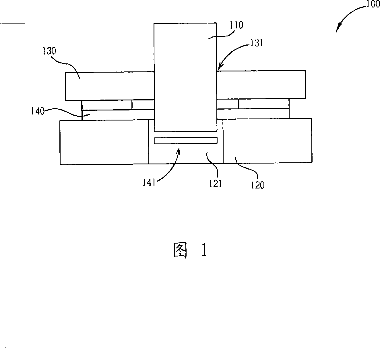
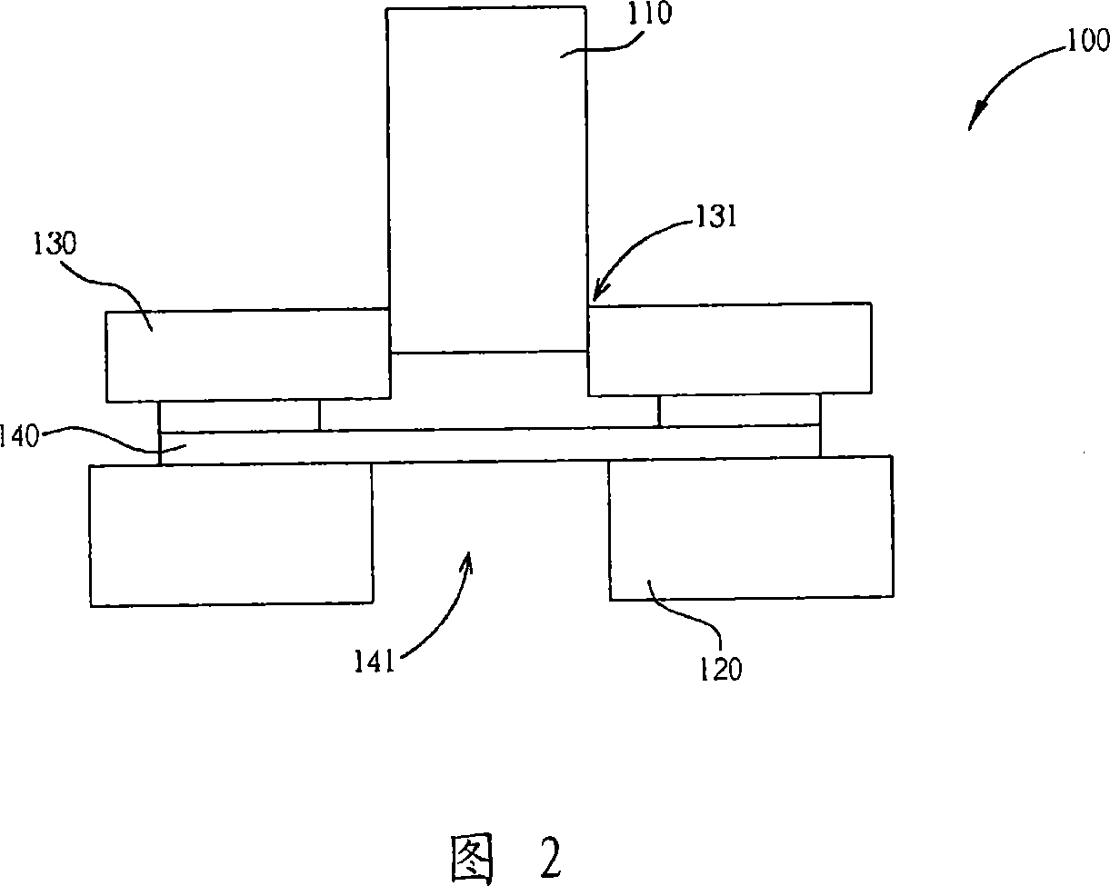
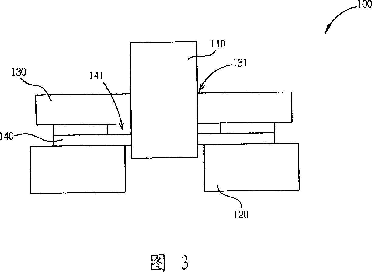
Therefore, when the punch leaves the narrow hole upwards, the problem of gold finger peeling and whitening of the substrate is solved.

Method used


Image

  • Punch and its using method
  • Punch and its using method
  • Punch and its using method

Examples


Embodiment Construction

[0026] The present invention provides a novel stamping machine and its use method, which are used to solve the problems of peeling of gold fingers on the base material and whitening of the base plate when the punch moves upward in the traditional stamping machine. The punching machine of the present invention uses a gas with pressure to fix the substrate, so as to avoid peeling off of golden fingers and whitening of the substrate. The novel stamping machine of the present invention can greatly improve the yield rate and competitiveness of products.

[0027] FIG. 5 illustrates a punching machine 200 of the present invention for processing a substrate 240 , including a punch 210 , a lower die 220 and a stripping member 230 . The punch 210 is used to form a narrow hole 241 on the substrate 240 . The base material 240 can be a substrate to be stamped such as a board-on-chip (BOC). On the substrate 240 there is an area where a narrow hole 241 is to be formed and a green paint (So...


PUM


Abstract

The invention discloses a stamping machine and a use method thereof. The stamping machine comprises a drift plug used for forming a narrow hole on a base material, a lower die which is provided with a lower die opening to receive the drift plug and supports the base material, and a stripper piece for fixing the position of the base material; the stripper piece is positioned above the lower die and provided with a stripper piece opening for receiving the drift plug and a plurality of air holes enclosing the stripper piece opening.

Description

technical field [0001] The present invention relates to a stamping machine and its use method, in particular to a stamping machine with air holes for fixing base materials and its use method. Background technique [0002] In the current production process of the substrate, a forming machine or a punching machine can be used for punching. Due to the high cost and low output of forming machines, punching machines are generally used for punching. [0003] As shown in FIG. 1 , a conventional stamping machine 100 includes a punch 110 , a lower die 120 and a stripping member 130 . When using the punching machine 100 to perform a punching process, the substrate 140 is placed on the lower mold 120 , and the lower mold 120 has a lower mold opening 121 for accommodating the punch 110 . The stripping member 130 located above the lower mold 120 is used to fix the position of the substrate 140 together with the lower mold 120 , and has a stripping member opening 131 for accommodating t...

Claims


Application Information

Patent Timeline
Patent Type & Authority Applications(China)
IPC IPC(8): H05K3/00B21D28/26B21D28/34B26F1/02B26F1/14
Inventor 王武昌
Owner ADVANCED SEMICON ENG INC
Why Eureka
Eureka Blog
Learn More