
Preparation method and application of self-supporting ordered structure membrane electrode

An ordered structure, membrane electrode technology, applied in the direction of electrodes, circuits, fuel cells, etc., can solve the problem of high interface resistance between electrocatalysts and ion-conducting membranes, difficulty in ensuring the quality uniformity of membrane electrodes, and difficulties in reducing ion transfer resistance, etc. Problems, achieve the effect of improving the degree of interface bonding, stabilizing the interface area, and reducing the film thickness

Inactive Publication Date: 2021-07-23
TSINGHUA UNIV
View PDF11 Cites 5 Cited by
  • Summary
  • Abstract
  • Description
  • Claims
  • Application Information

AI Technical Summary

Problems solved by technology

However, there are several common problems in the existing methods
1) In the membrane electrode preparation process, the finished solid ion-conducting membrane is used, and the two are combined through certain technological means, which often leads to the problem of high interface resistance between the electrocatalyst and the ion-conducting membrane; 2) The catalyst particles, binder Mixing slurry, using spraying or transfer printing methods, combined with ion-conducting membranes, there are problems such as catalyst particle aggregation and peeling during use, and it is difficult to maintain the long-term stability of membrane electrodes; 3) Multiple preparation steps are required, resulting in actual production The process is complicated and it is difficult to ensure the uniformity of membrane electrode quality
In addition, because the preparation process requires sufficient mechanical strength, it is difficult to achieve ultra-thin ion-conducting membranes, which makes it difficult to reduce the resistance of ion transfer.
In view of the prior art methods, it is difficult to ensure the tight combination between the catalyst and the polymer membrane on the microscopic scale

Method used


Image

  • Preparation method and application of self-supporting ordered structure membrane electrode
  • Preparation method and application of self-supporting ordered structure membrane electrode
  • Preparation method and application of self-supporting ordered structure membrane electrode

Examples


Embodiment 1

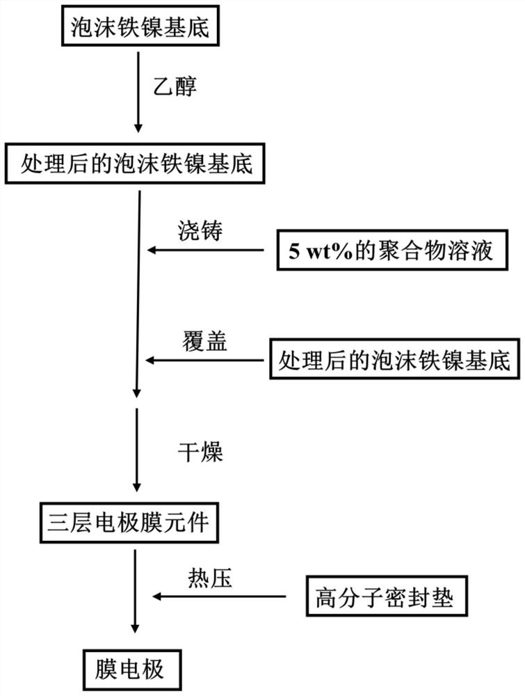
[0046] 1) use the foamed iron-nickel alloy as the catalytic electrode, which is cleaned and dried in ethanol solution;

[0047] 2) dissolving the polybenzimidazole macromolecule in N-methylpyrrolidone to make a solution with a concentration of 5% by weight;

[0048] 3) casting the polybenzimidazole solution prepared in step 2) on the surface of the foamed iron-nickel alloy treated in step 1), and spreading it on the surface of the foamed iron-nickel alloy after drooling;

[0049] 4) covering the foamed iron-nickel alloy treated in step 1) on the polybenzimidazole solution obtained in step 3), heating and drying to obtain a device in which the foamed iron-nickel alloy sandwiches a polybenzimidazole film;

[0050] 5) Using a hot pressing method to connect a polymer sealing gasket to the periphery of the device produced in step 4) to obtain a membrane electrode.

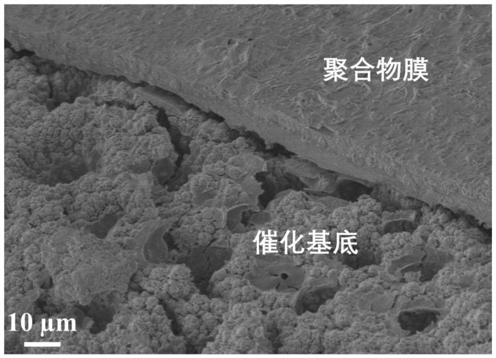
[0051] From figure 2 It can be clearly seen from the electron microscope image that the interface between the memb...

Embodiment 2

[0057] 1) use the foamed iron-nickel alloy as the catalytic electrode, which is cleaned and dried in ethanol solution;

[0058] 2) Using ethanol as a solvent, prepare a perfluorosulfonic acid resin solution with a concentration of 5% by weight, and cast it on the surface of the foamed iron-nickel alloy treated in step 1), and spread it on the foamed iron-nickel alloy after drooling surface;

[0059] 3) covering the foamed iron-nickel alloy treated in step 1) on the perfluorosulfonic acid resin solution obtained in step 2), heating and drying to obtain a device with a perfluorosulfonic acid resin film sandwiched between the foamed iron-nickel alloy;

[0060] 4) Using a hot pressing method to connect a polymer sealing gasket to the periphery of the device produced in step 3) to obtain a membrane electrode.

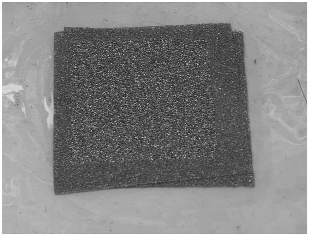
[0061] In kind such as image 3 As shown, the surface of the membrane electrode is smooth and flat, and the edge of the perfluorosulfonic acid resin solution is transparen...

Embodiment 3

[0063] 1) use the foamed iron-nickel alloy as the catalytic electrode, which is cleaned and dried in ethanol solution;

[0064] 2) dissolving the polyvinylidene fluoride polymer in dimethyl sulfoxide to prepare a polymer solution with a concentration of 5% by weight;

[0065] 3) spraying the polyvinylidene fluoride solution prepared in step 2) on the surface of the foamed iron-nickel alloy treated in step 1);

[0066] 4) covering the foamed iron-nickel alloy treated in step 1) on the polyvinylidene fluoride solution obtained in step 3), heating and drying to obtain a device with a polyvinylidene fluoride film sandwiched in the middle of the foamed iron-nickel alloy;

[0067] 5) Using a hot pressing method to connect a polymer sealing gasket to the periphery of the device produced in step 4) to obtain a membrane electrode.


PUM

PropertyMeasurementUnit
thicknessaaaaaaaaaa

Abstract

The invention discloses a preparation method and application of a self-supporting ordered structure membrane electrode, and belongs to the technical field of electro-catalysis membrane reactors. The method comprises: taking a porous structure solid material with an electro-catalysis function as a catalytic electrode; preparing a polymer of an ion conducting membrane into a polymer solution; salivating the polymer solution on the surface of the solid material to form a uniform thin layer, so that the surface is completely covered, the holes of the solid material are infiltrated, the interface area of the solid material and the polymer solution is increased, and active sites of the electrocatalyst are fully exposed; and covering another solid material on the polymer thin layer, heating and drying, and sealing to obtain the membrane electrode. According to the invention, the thickness of the film can be reduced by regulating and controlling the thickness of the film casting liquid coating, the ultrathin film with the bent surface is formed, the film is tightly attached along the uneven electrode surface, and the bonding firmness is enhanced; and the membrane electrode is of a three-dimensional surface structure, a larger interface area is provided, ion transfer is facilitated, and the performance of the membrane electrode is improved.

Description

technical field [0001] The invention belongs to the technical field of electrocatalytic membrane reactors, and in particular relates to a preparation method and application of a membrane electrode with a self-supporting ordered structure. Background technique [0002] Membrane electrode is a high-efficiency electrochemical reaction functional device. It is usually composed of three parts: gas diffusion layer (GDL), catalytic layer (CL) and ion-conducting membrane. The two sides of the ion-conducting membrane are catalytic layers. Depending on the application scenario, the load is different. electrocatalyst. The device is used in fuel cells and electrolyzed water to produce hydrogen. It integrates the functions of electrochemical reaction, energy conversion and material transport into one component, which not only reduces the number of components in the electrochemical device, improves the integration and reliability of the device, but also realizes The "zero gap" combinatio...

Claims


Application Information

Patent Timeline
Patent Type & Authority Applications(China)
IPC IPC(8): H01M8/1004H01M8/18C25B9/23C25B1/04C25B11/032
CPCH01M8/1004H01M8/188C25B1/04Y02P70/50Y02E60/36Y02E60/50
Inventor 王保国万磊
Owner TSINGHUA UNIV
Learn More