Sheet cutting device and sheet cutting method

A cutting device and sheet technology, which is applied in the direction of manufacturing tools, program control manipulators, chucks, etc., can solve the problems of operators touching tools and being injured, and achieve the effects of reducing danger, improving cutting ability, and easy cutting

Active Publication Date: 2008-08-06
LINTEC CORP
View PDF1 Cites 3 Cited by
  • Summary
  • Abstract
  • Description
  • Claims
  • Application Information

AI Technical Summary

Problems solved by technology

[0008] In addition, there is also the following shortcoming, that is, because the cutting device is located on the wafer, in the case of a problem with the device, when performing the operation of picking up the wafer or the maintenance of the equipment, the operator's hand is likely to touch the blade of the cutter, causing Injuried

Method used


Image

  • Sheet cutting device and sheet cutting method
  • Sheet cutting device and sheet cutting method
  • Sheet cutting device and sheet cutting method

Examples


Embodiment Construction

[0066] Hereinafter, embodiments of the present invention will be described with reference to the drawings.

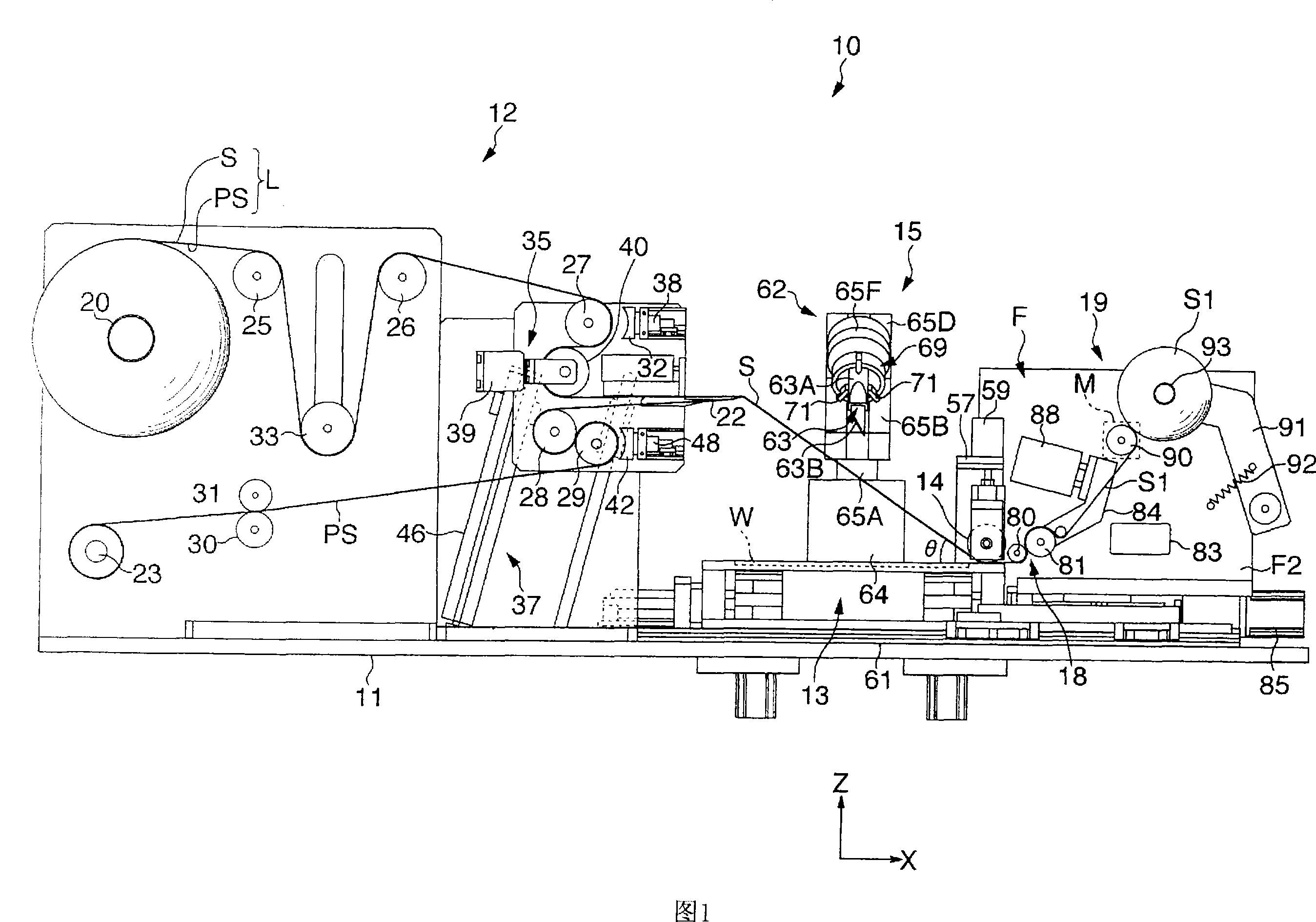
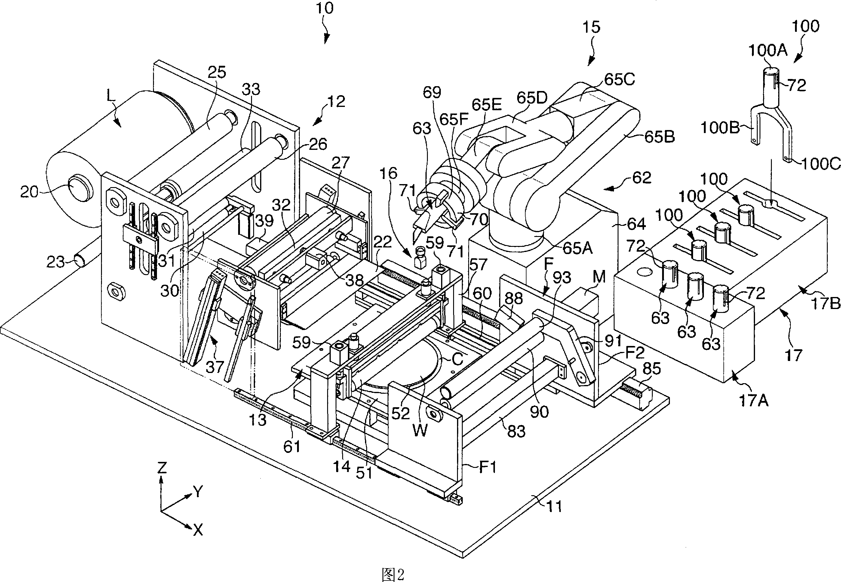
[0067] FIG. 1 is a schematic front view showing a sheet sticking device to which the cutting device according to the present embodiment is applied, and FIG. 2 is a schematic perspective view thereof. In these two figures, the composition of the sheet sticking device 10 includes: a sheet lead-out unit 12 arranged on the upper part of the base 11; a support table 13 supporting a wafer W as an object to be pasted; Adhesive sheet S, and stick it to the push roller 14 on the wafer W; after sticking the adhesive sheet S to the wafer W, a cutting device that cuts the adhesive sheet S along the outer edge of the wafer W 15; the inspection mechanism 16 (referring to FIG. 2 ) for inspecting the cutter blade 63 described later of the cutting device 15; the storage device 17 for the cutter blade 63 etc.; A peeling device 18 for peeling the upper surface; a winding device 19 for wi...


PUM


Abstract

A cutting device that, after a sheet is stuck on a wafer on a sticking table, cuts the sheet along the outer edge of the wafer. The cutting device includes a robot body disposed besides the sticking table and a cutter blade supported by a tool holding chuck positioned at the front end of the robot body. The cutter blade is detachably attached to the tool holding chuck so as to be replaceable and is arranged so as to cut the sheet in a state that the posture thereof is adjusted along a preset movement track.

Description

technical field [0001] The present invention relates to a sheet cutting device and cutting method. More specifically, the present invention relates to a sheet cutting device and cutting method capable of cutting a sheet with high precision while cutting a sheet along a preset trajectory. Background technique [0002] Conventionally, a protective sheet for protecting the circuit surface of a semiconductor wafer (hereinafter referred to as "wafer") is pasted, or an adhesive sheet with heat-sensitive adhesiveness is pasted on the back or the front surface. [0003] As a pasting method of the above-mentioned sheet, the following pasting method is known (for example, refer to Patent Document 1): one method is to use a tape-shaped release sheet temporarily bonded with a planar sheet corresponding to the shape of the wafer. Web (stock sheet) from which the sheet is peeled off with a release sheet and pasted on the wafer; or another method is to use a web with a tape-shaped sheet te...

Claims


Application Information

Patent Timeline
Patent Type & Authority Applications(China)
IPC IPC(8): B26D7/10B25J9/06B26D7/08B26D7/22
CPCB26D7/015H01L21/67092B25J11/0055B26D1/1535B25J15/04B26D3/10B26D7/2614H01L21/67132B26F1/3846B26D7/22Y10T156/12Y10T83/0393Y10T83/0467Y10T83/0543Y10T83/8798Y10T83/8821Y10T83/9457B25J9/06B26D7/08B26D7/10H01L21/02
Inventor 野中英明中田干杉下芳昭小林贤治
Owner LINTEC CORP
Why Eureka
Try Eureka