Optical fiber sensor

An optical fiber sensor and optical fiber technology, which is applied in cladding optical fiber, using optical devices to transmit sensing components, instruments, etc., can solve problems such as light loss

Inactive Publication Date: 2008-08-06
DENSO CORP +1
View PDF1 Cites 4 Cited by
  • Summary
  • Abstract
  • Description
  • Claims
  • Application Information

AI Technical Summary

Problems solved by technology

This interface reflection also results in loss of light

Method used


Image

  • Optical fiber sensor
  • Optical fiber sensor
  • Optical fiber sensor

Examples


Embodiment Construction

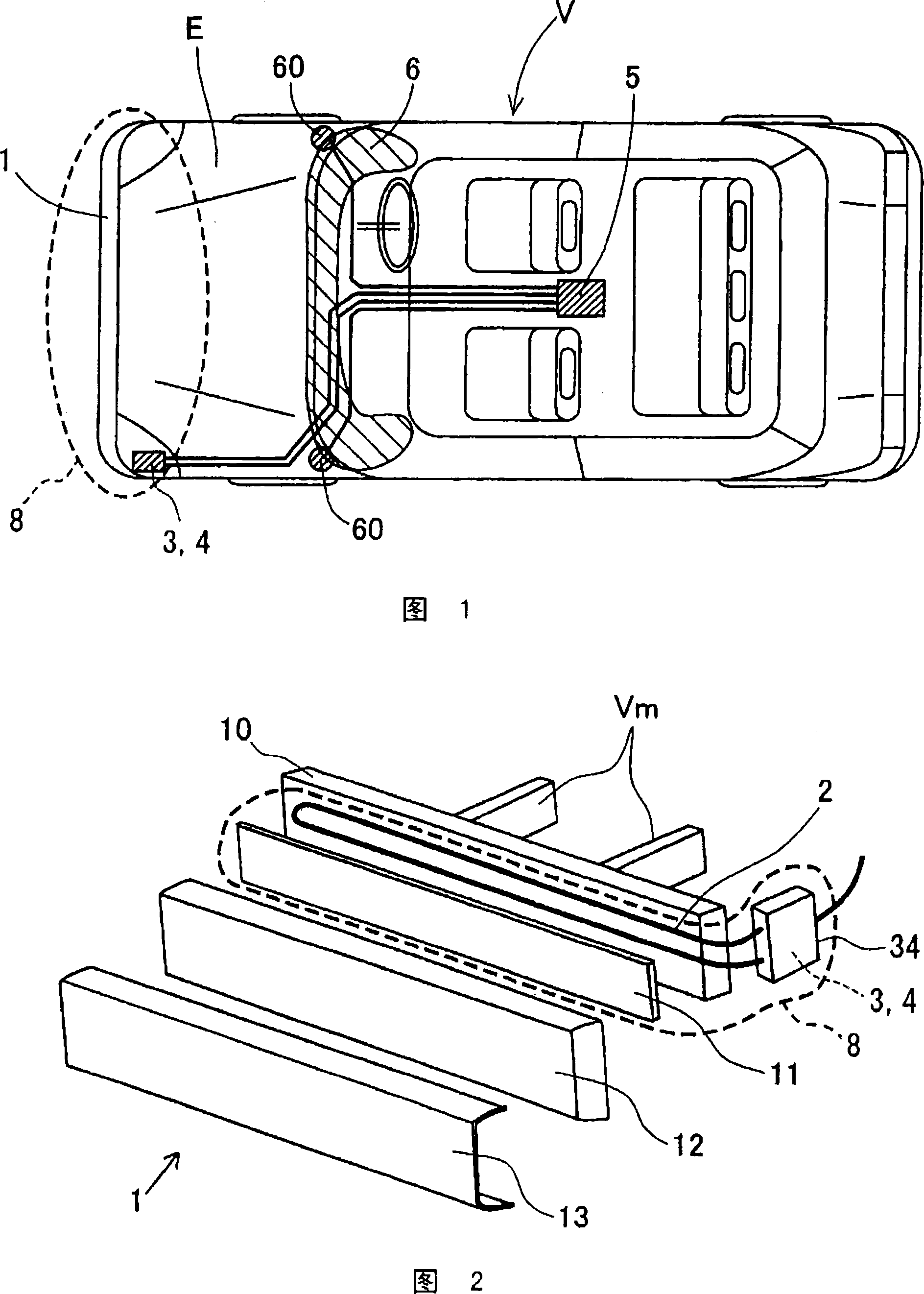
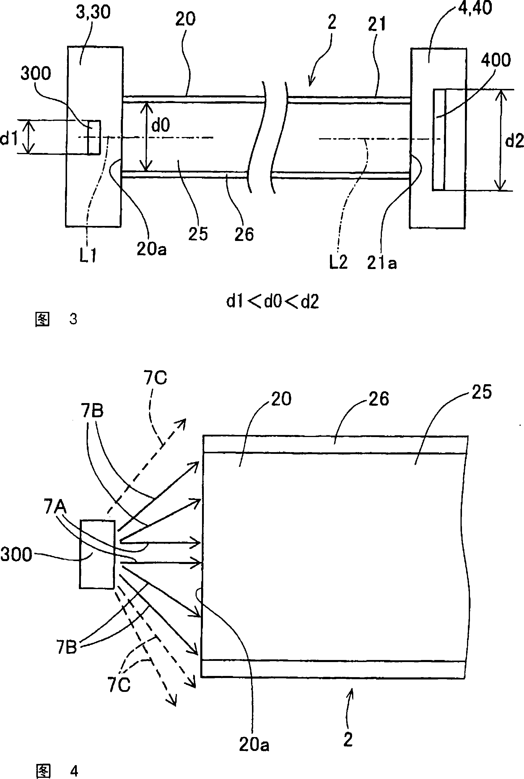
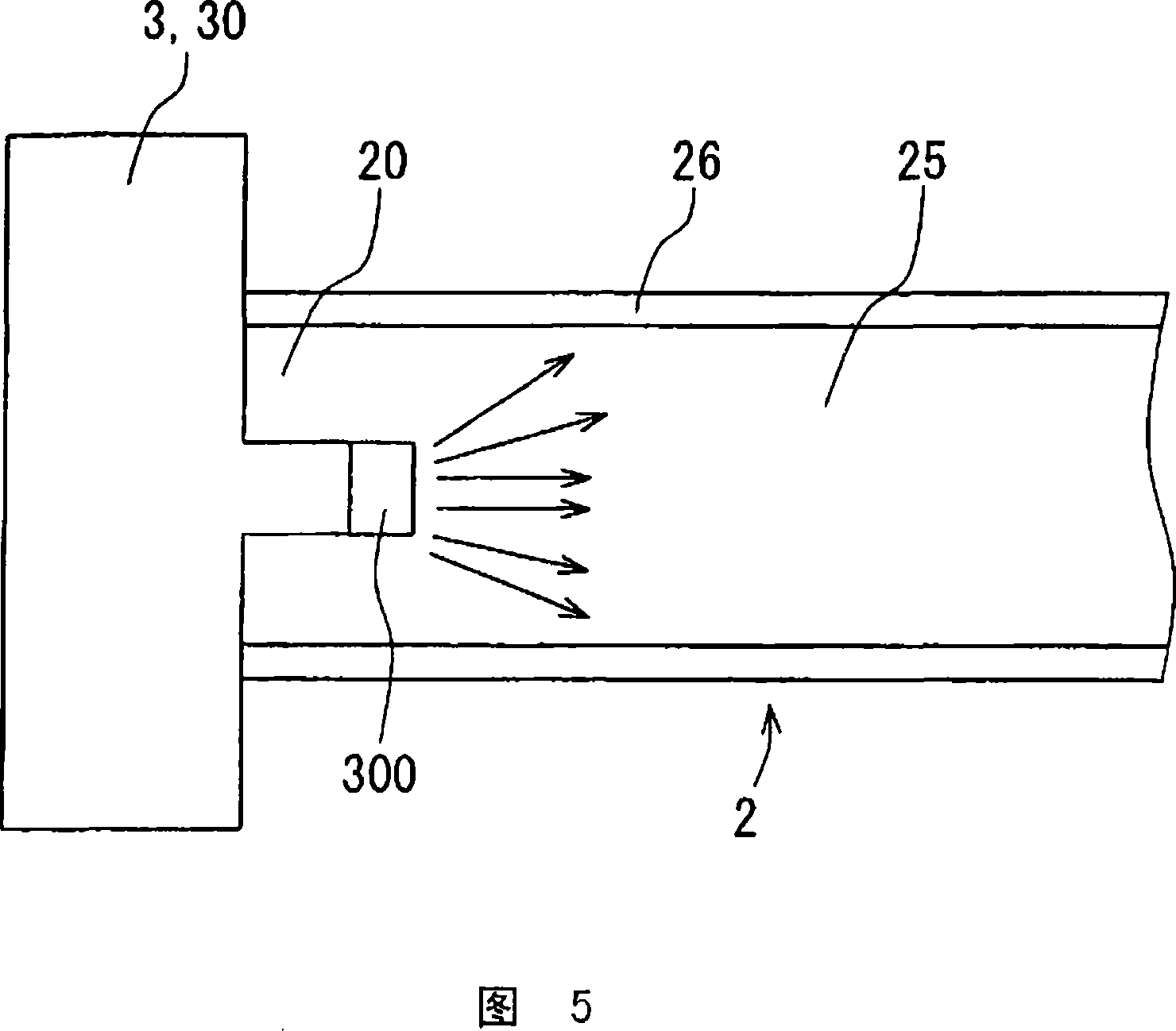
[0017] The optical fiber sensor of the present invention has an optical fiber, a light emitting member connected to a first end of the optical fiber, and a light receiving member connected to a second end of the optical fiber. The light emitting member emits light toward the first end of the optical fiber. Light is transmitted from the first end to the second end in the optical fiber, and is irradiated toward the light receiving member from the second end. Fiber optic sensors determine changes in light that occur when light passes through an optical fiber based on characteristics of light emitted from a light emitting member such as intensity and phase and characteristics of light received in a light receiving member. In addition, the fiber optic sensor calculates the stress applied to the fiber based on the change in light.

[0018] When stress is applied to the fiber, the fiber deforms and the light transfer characteristics change at the deformed portion of the fiber. At t...


PUM


Abstract

An optical fiber sensor (8) has an optical fiber (2) and, a light emitting member (3) connected to a first end (20) of the optical fiber (2), a light receiving member (4) connected to a second end (21) of the optical fiber (2). The light emitting member (3) has a light emitting portion (300) through which light is radiated to the first end (20) of the optical fiber (2). The light receiving member (4) has a light receiving portion (400) for receiving light radiated from the second end (21) of the optical fiber (2). The light emitting portion (300) is smaller than a sectional area of a core portion (25) of the optical fiber (2).

Description

technical field [0001] The invention relates to fiber optic sensors with optical fibers. Background technique [0002] In recent years, vehicles have been required to improve not only the safety of passengers but also the safety of pedestrians colliding with the vehicles. It is known to provide pedestrian protection devices on vehicles for reducing injury to pedestrians who may fall onto the hood of the vehicle as a result of a collision. In pedestrian protection devices, it is important to determine the collision of pedestrians. As one of the ways of detecting pedestrian collision, it is known to use a collision detection sensor with an optical fiber sensor. This collision detection sensor is attached to, for example, a bumper of a vehicle. [0003] Fiber optic sensors detect stress applied to an optical fiber based on changes in the light transmitted in the optical fiber. Generally, an optical fiber is deformed by external stress, and the light transmission characteris...

Claims


Application Information

Patent Timeline
Patent Type & Authority Applications(China)
IPC IPC(8): G01D5/26G01D5/353G01L1/24
CPCG01L1/242G01D5/353G02B6/02
Inventor 大高孝治伊豫田纪文宫田裕次郎家中龙太郎高桥浩幸
Owner DENSO CORP
Why Eureka
Try Eureka